Wiring Material, Method for Manufacturing Such Wiring Material and Resistance Welding Apparatus Used in Such Manufacturing Method

Active Publication Date: 2008-04-03
HITACHI CABLE
View PDF5 Cites 25 Cited by
  • Summary
  • Abstract
  • Description
  • Claims
  • Application Information

AI Technical Summary

Benefits of technology

[0070] According to the present invention, it is possible to provide the wiring material with high connection reliability in

Problems solved by technology

However, in the case where the wiring material is fabricated by punching the copper plate, there is a disadvantage in that material cost becomes high due to a lot of needless parts formed by punching to have the circular shape.
Further, the process becomes complicated since the step of integrally molding one set of two or three copper plates by resin mold is required.
Still further, there is another disadvantage in that bad insulat

Method used


Image

  • Wiring Material, Method for Manufacturing Such Wiring Material and Resistance Welding Apparatus Used in Such Manufacturing Method
  • Wiring Material, Method for Manufacturing Such Wiring Material and Resistance Welding Apparatus Used in Such Manufacturing Method
  • Wiring Material, Method for Manufacturing Such Wiring Material and Resistance Welding Apparatus Used in Such Manufacturing Method

Examples


example 1

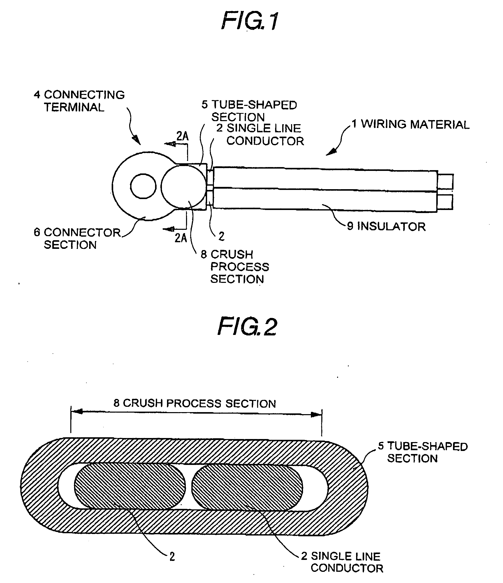
[0171] A Sn-plating with a thickness of 0.5 μm was provided on a copper wire with a diameter of 2.6 mm, and an insulator (PFA) with a thickness of 0.3 mm was provided thereon as an insulation coating. The insulator at a tip portion of this insulation coated copper wire was peeled off along a length of 13 mm to expose the copper wire, to provide a Sn-plated copper wire (single line conductor) 2.

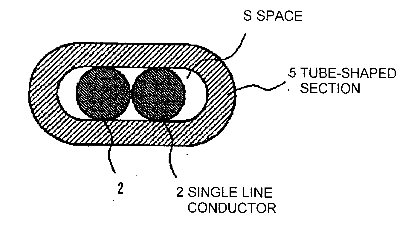
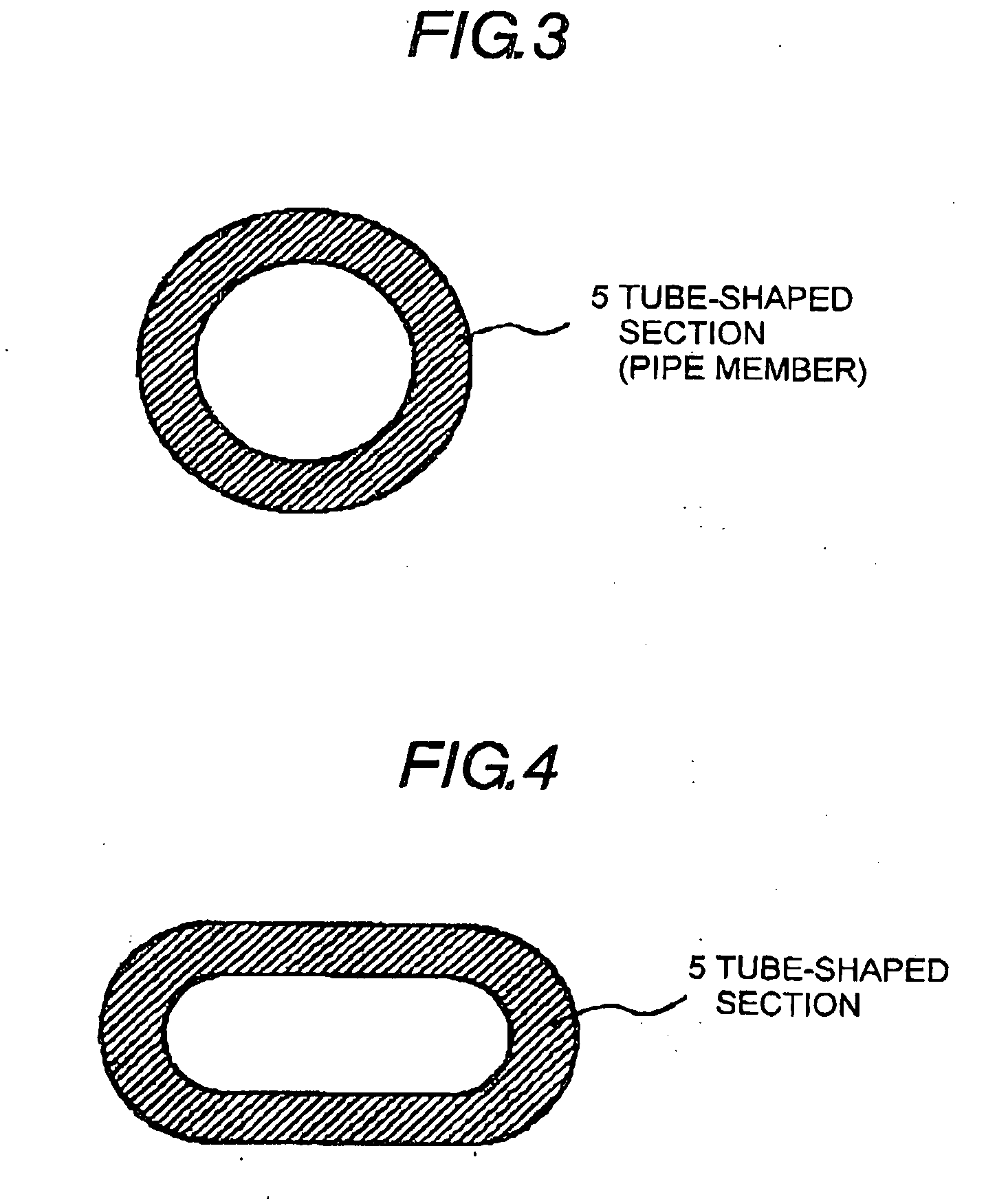
[0172] Next, a copper plate with a thickness of 1.0 mm was press-molded to provide a terminal tapered configuration and bent to form a part (tube-shaped section 5) for gripping the single line conductor 2, then a matching part was brazed to form a terminal barrel section with a true circle cross section having an opening with a diameter of 3.4 mm, and a terminal face was Sn-plated. By conducting the press-molding on the above device, a connecting terminal 44 comprising copper with an approximately oval cross section was formed.

[0173] Two Sn-plated copper wires (single line conductors) 2 were...

example 2

[0177] The wiring material was completed under conditions same as those of Example 1 except that the round-shape at the tip portion of the upper welding electrode 14 had a radius of 1.5 mm, and the electrode angle was 70°.

example 3

[0178] The wiring material was completed under conditions same as those of Example 1 except that the round-shape at the tip portion of the upper welding electrode 14 had a radius of 1.75 mm, and the electrode angle was 75°.


PUM

PropertyMeasurementUnit
Lengthaaaaaaaaaa
Lengthaaaaaaaaaa
Angleaaaaaaaaaa

Abstract

A wiring material is provided by electrically connecting a connecting terminal with two single line conductors arranged in parallel. The connecting terminal is provided with a tube-shaped section for storing two single line conductors, the two single line conductors are inserted into the tube-shaped section, resistance welding is performed by carrying electricity from the external of the tube-shaped section in a status where the tube-shaped section and the single line conductors are mutually brought into contact, and the connecting terminal is electrically connected with the two single line conductors.

Description

FIELD OF THE INVENTION [0001] The present invention relates to wiring material, method for manufacturing such wiring material and resistance welding apparatus used in such manufacturing method to be used for vehicle apparatuses, and more particularly, to wiring material, method for manufacturing such wiring material and resistance welding apparatus used in such manufacturing method with the use of an insulation-coated single line conductor. BACKGROUND OF THE INVENTION [0002] As a cable for vehicle, there is a wiring material for feeding to a stator coil of a motor, for example. Conventionally, the wiring material is manufactured by extending enamel wires wound around a stator core to a feeding section, bundling plural enamel wires, and connecting a bundle of enamel wires to the feeding section by TIG (Tungsten Inert Gas) welding or soldering. [0003] In accordance with spread of hybrid vehicles and advance in electrification of apparatuses, higher voltage is applied to and higher cur...

Claims


Application Information

Patent Timeline
IPC IPC(8): H01R4/60B23K11/30H01R43/02
CPCH01R4/023Y10T29/49172Y10T29/49181Y10T29/49183Y10T29/49179Y10T29/49227Y10T29/49176Y10T29/4919
Inventor SUMI, TORUIWASITA, TSUKASAEGAMI, KENICHIWATANABE, KAZUYUKIOKIKAWA, HIROSHI
Owner HITACHI CABLE
Why Eureka
Try Eureka