
Orthopaedic component manufacturing method and equipment

a manufacturing method and orthopaedic technology, applied in the field of orthopaedics, can solve the problems of stress on joints or damage to joints in the body, wear and tear of cartilage, and damage to other connective tissues such as tendons or ligaments, so as to prolong the life of the orthopaedic implant, reduce break-in wear, and smoke average surface finish

Active Publication Date: 2008-04-03
DEPUY PROD INC
View PDF22 Cites 13 Cited by
  • Summary
  • Abstract
  • Description
  • Claims
  • Application Information

AI Technical Summary

Benefits of technology

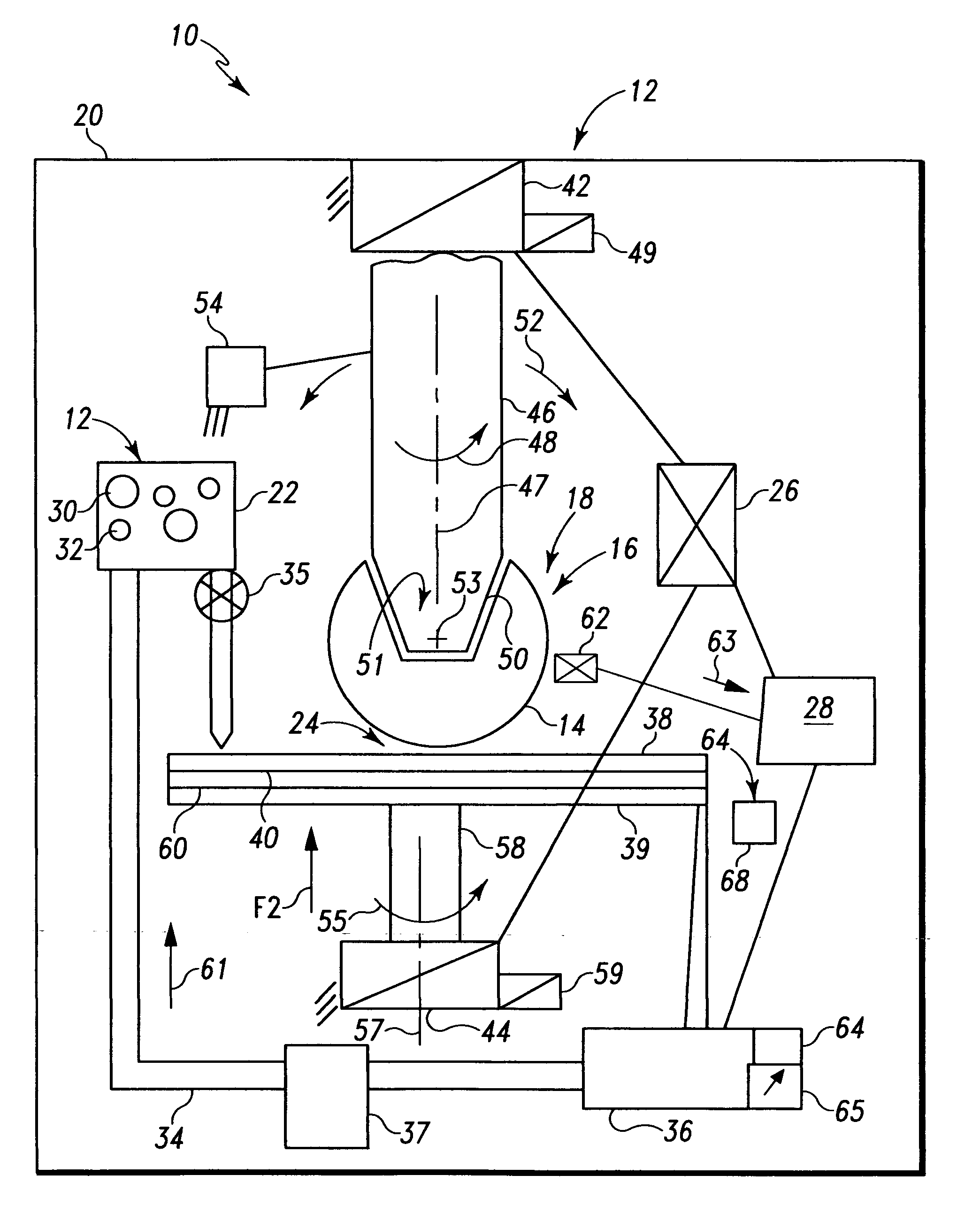
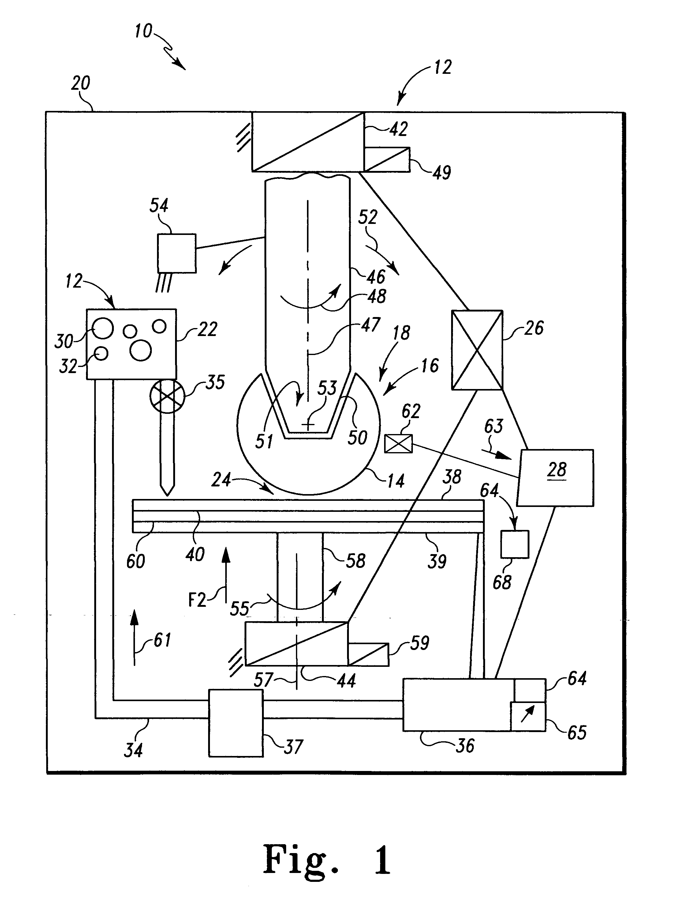
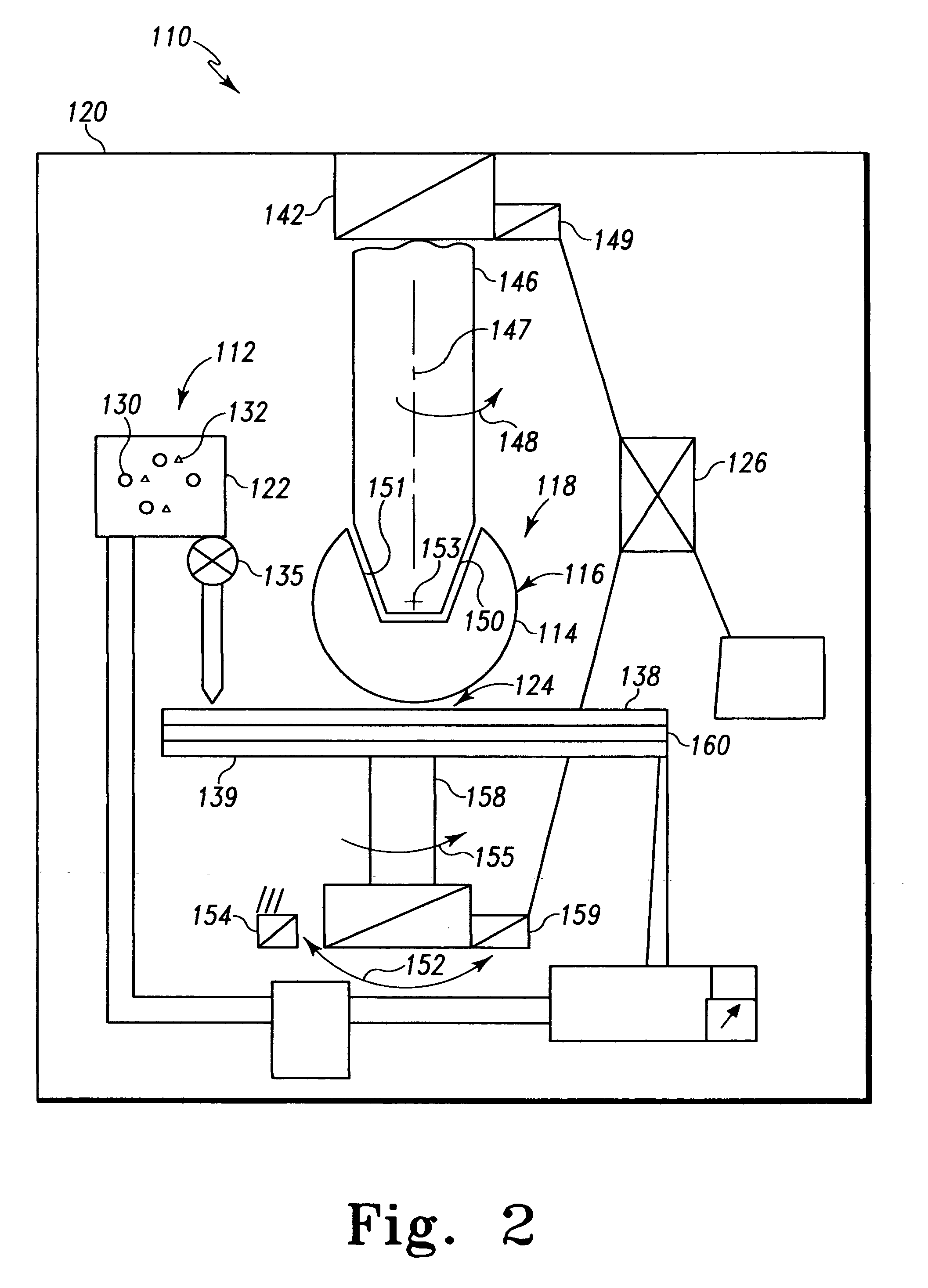
[0033]According to an aspect of the present invention, a method of reducing the surface roughness of articulating surfaces of orthopaedic implants is provided. The method includes the steps of providing an abrasive particle providing a chemical including at least one of an oxidant, a corrosion inhibitor, a complexing agent and a surfactant, combining the chemical with the abrasive particle to form a slurry, and polishing the implant with the slurry.
[0060]The technical advantages of the present invention also include the ability to provide a better conformance to surface geometries for orthopedic articulating surfaces and in particular, metal on metal articulating surfaces to reduce break-in wear and provide longer orthopedic implant life. For example, according to another aspect of the present invention a method of reducing the surface roughness and to improve surface geometries of articulating surfaces of orthopedic implants includes the steps of providing an abrasive particle, providing a chemical including one of an oxidant, a corrosion inhibitor, a complexing agent and a surfactant. A third step of mixing the abrasive particle with the chemical to form a slurry, a fourth step of providing a manipulator to provide the implant in a plurality of orientations and a fifth step of polishing the implant with the slurry with the manipulator positioning the implant in a variety of positions. Thus the present invention provides for quicker polish times and less labor to polish and articulating surface of an orthopedic implant.

Problems solved by technology

The joints in the body are stressed or can be damaged in a variety of ways.
Over time, the normal use of a joint may wear down the cartilage and bring the moving bones in a direct contact with each other.
In contrast, in normal use, a trauma to a joint, such as the delivery of a large force, from an accident, for example, an automobile accident, may cause considerable damage to the bones, the cartilage or to other connective tissue such as tendons or ligaments.
Dimensional errors and surface finish imperfections may cause the prosthesis to prematurely wear.
The components that wear on the prosthesis, particularly those that wear rapidly, may lead to reactions with the tissues of the body.
Osteolysis can damage soft tissue and further complicate the replacement of the prosthesis.
These prior art attempts at providing improved geometry and finish to the articulating surface of a prosthetic component are slow and inaccurate.
Further, attempts to improve the finish on the part may affect its geometry or shape.
Imperfections in shape and or finish may greatly reduce the operating life of the prosthesis and may lead to osteolysis.
On the other hand, little progress has been made in reducing surface finish values below 10 nm in a production environment.
A mechanically polished surface yields an abundance of scratches, strains, metal debris and embedded abrasives, and always distorts the metal surface.
Burnishing metal by lapping or buffing decreases the rms roughness of a surface, but it never completely removes the debris and damaged metal caused by mechanical polishing.

Method used


Image

  • Orthopaedic component manufacturing method and equipment
  • Orthopaedic component manufacturing method and equipment
  • Orthopaedic component manufacturing method and equipment

Examples


Embodiment Construction

[0087]Embodiments of the present invention and the advantages thereof are best understood by referring to the following descriptions and drawings, wherein like numerals are used for like and corresponding parts of the drawings.

[0088]In CMP of metals, it is generally found necessary to add an oxidizer. This is equivalent to increasing the electrode potential. By proper selection of pH and oxidizer, the metal removal rates and surface finish may be optimized.

[0089]Other chemical modifiers that may be added to the abrasive slurry include buffers, surfactants, complexing agents and inhibitors. Buffering reagents help maintain a constant pH during the CMP process. Complexing agents tie up or sequester material removed in the CMP process. This has the effect of changing the equilibrium concentration and can increase removal rates. Surfactants change the surface tension between the abrasive and the surrounding solution and increase the wetting of the slurry to the polished object. Finally,...


PUM

PropertyMeasurementUnit
angleaaaaaaaaaa
rms surface roughnessaaaaaaaaaa

Abstract

A method of reducing the surface roughness of articulating surfaces of orthopaedic implants is provided. The method includes the steps of providing an abrasive particle providing a chemical including at least one of an oxidant, a corrosion inhibitor, a complexing agent and a surfactant, combining the chemical with the abrasive particle to form a slurry, and polishing the implant with the slurry.

Description

TECHNICAL FIELD OF THE INVENTION[0001]The present invention relates generally to the field of orthopaedics, and more particularly, to an implant for use in arthroplasty.BACKGROUND OF THE INVENTION[0002]The skeletal system includes many long bones that extend from the human torso. These long bones include the femur, fibula, tibia, humerus, radius and ulna.[0003]A joint within the human body forms a juncture between two or more bones or other skeletal parts. The ankle, hip, knee, shoulder, elbow and wrist are just a few examples of the multitude of joints found within the body. As should be apparent from the above list of examples of joints, many of the joints permit relative motion between the bones. For example, the motion of sliding, gliding, and hinge or ball and socket movements may be had by a joint. For example, the ankle permits a hinge movement, the knee allows for a combination of gliding and hinge movements and the shoulder and hip permit movement through a ball and socket ...

Claims


Application Information

Patent Timeline
Patent Type & Authority Applications(United States)
IPC IPC(8): B24C3/26A61B17/00
CPCA61F2/30767B24B37/02A61F2/32A61F2/34A61F2/36A61F2/3662A61F2/3859A61F2/389A61F2/40A61F2/4059A61F2/4081A61F2002/30187A61F2002/30332A61F2002/30364A61F2002/30596A61F2002/30841A61F2002/30878A61F2002/30892A61F2002/30894A61F2002/30934A61F2002/3611A61F2002/3625A61F2002/365A61F2002/4018A61F2002/4029A61F2002/4037A61F2002/443A61F2220/0033A61F2230/0034B24B1/00A61F2/3094A61F2002/30594
Inventor ERNSBERGER, CRAIG N.
Owner DEPUY PROD INC
Learn More