

Synthesis of aligned carbon nanotubes on double-sided metallic substrate by chemical vapor depositon
a technology of carbon nanotubes and metallic substrates, applied in the direction of crystal growth process, polycrystalline material growth, chemically reactive gases, etc., can solve the problems of structural damage and enhancement still far below expectations
- Summary
- Abstract
- Description
- Claims
- Application Information
AI Technical Summary
Benefits of technology
Problems solved by technology
Method used
Image

Examples
example 1
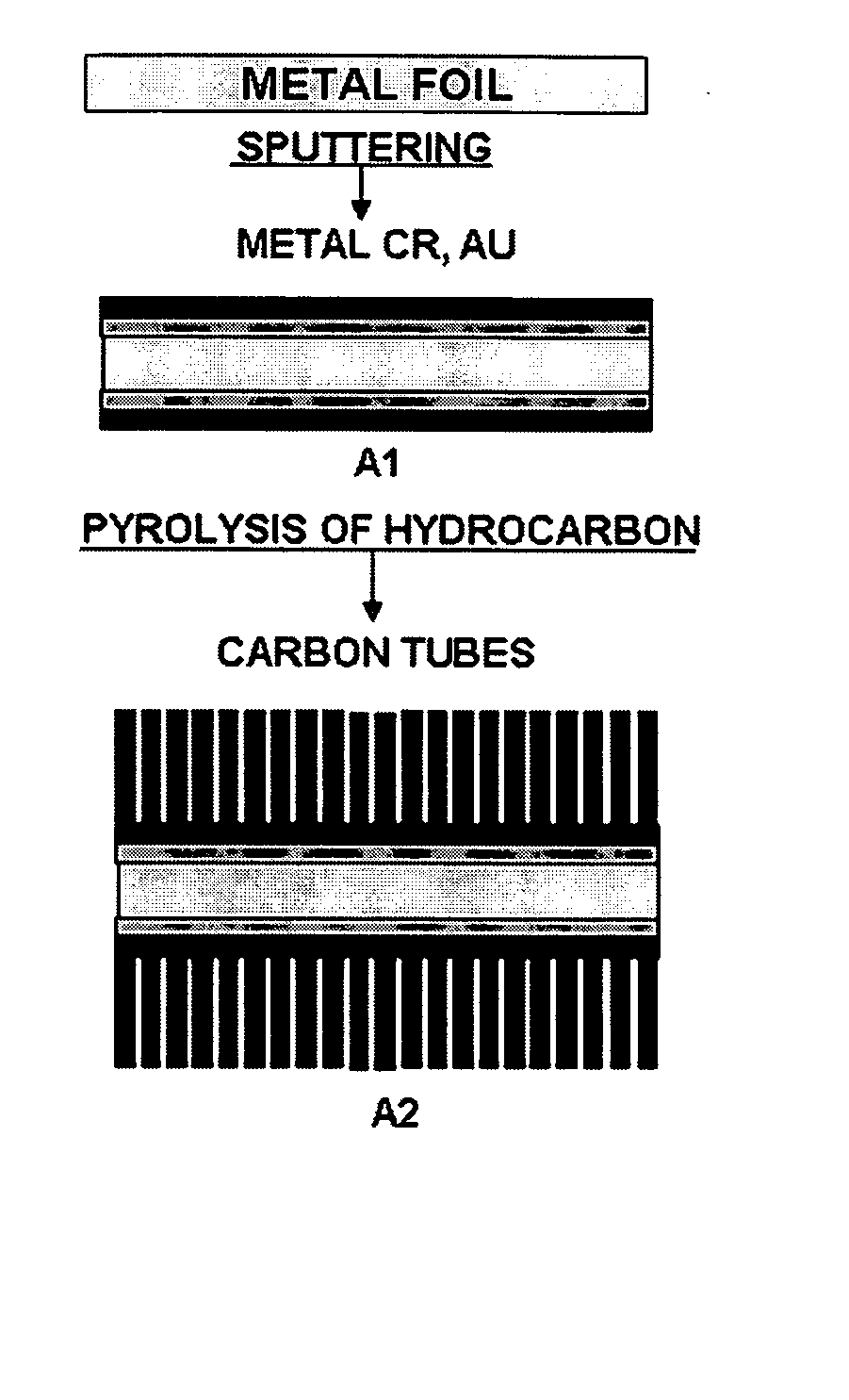
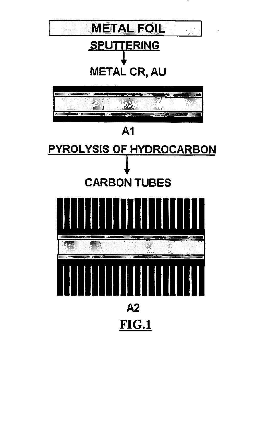
[0028] Aligned CNTs were produced by using a chemical vapor deposition system, which included a horizontal quartz tube (2.5 cm diameter; 70 cm long) housed in a sing-zone furnace (Carbolite, UK). The substrate was placed in the middle of the heating zone, which had the maximum temperature of 750° C. The following conditions were used in experiments where a different volume of water was added into the reaction system:
[0029] Substrate: Thin Cr film (12 nm) and Au film (20 nm) were deposited on both sides of the silicon wafer.
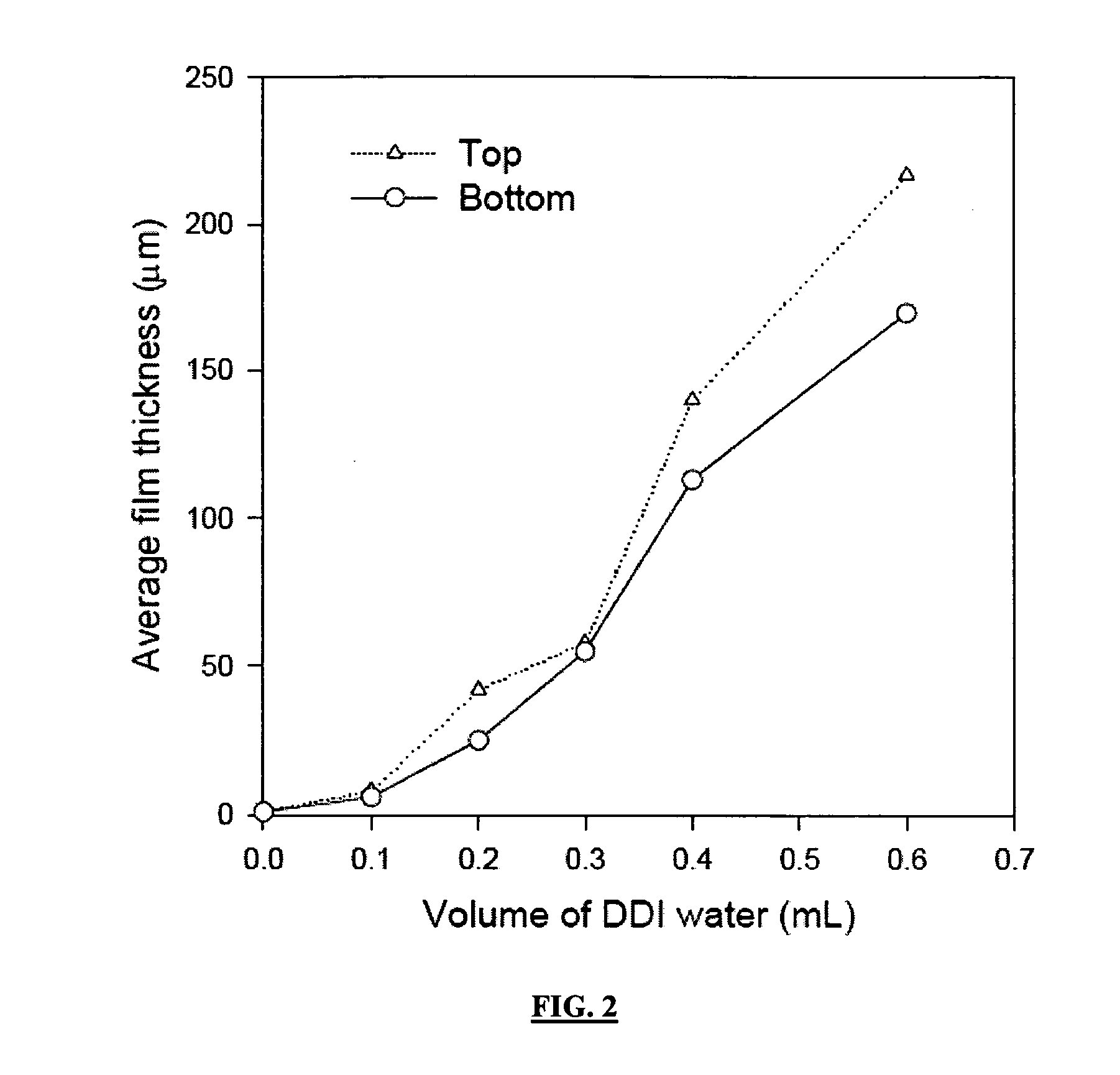
[0030] Volume of water added: 0 mL, 0.2 mL, 0.3 mL, 0.4 mL, 0.6 mL
[0031] Amount of catalyst: 150 mg ferrocene
[0032] Growth temperature: 750° C.
[0033] Growth time: 20 min
[0034] Flow rate of argon: 200 sccm
[0035] Flow rate of hydrogen: 16 sccm
[0036] Flow rate of ethylene: 40 sccm
[0037] Under the above conditions, different thicknesses of CNT films were synthesized on double-sided metallic substrate. The relationship between the thickness of CNT film and the...
example 2
[0038] The following conditions were used in experiments where different growth temperatures were chosen:
[0039] Substrate: Thin Cr film (12 nm) and Au film (20 nm) were deposited on both sides of the silicon wafer.
[0040] Volume of water added: 0.4 mL
[0041] Amount of catalyst: 150 mg ferrocene
[0042] Growth temperature: 725° C., 750° C., 775° C., 800° C.
[0043] Growth time: 20 min
[0044] Flow rate of argon: 200 sccm
[0045] Flow rate of hydrogen: 16 sccm
[0046] Flow rate of ethylene: 40 sccm
[0047] Under the above conditions, different thicknesses of CNT films were synthesized on double-sided metallic substrate. The relationship between the thickness of CNT film and growth temperature is shown in FIG. 3. It is seen that a thicker aligned CNT film can be synthesized by higher temperature. Temperature is a factor for aligned CNT synthesis, the thickness of CNT film can be controlled by varying CVD growth temperature.
example 3
[0048] The following conditions were used in experiments where different amounts of ferrocene were chosen as catalyst:
[0049] Substrate: Thin Cr film (12 nm) and Au film (20 nm) were deposited on both sides of the silicon wafer.
[0050] Volume of water added: 0.4 mL
[0051] Amount of catalyst: 30 mg, 100 mg, 150 mg, 200 mg ferrocene
[0052] Growth temperature: 750° C.
[0053] Growth time: 20 min
[0054] Flow rate of argon: 200 sccm
[0055] Flow rate of hydrogen: 16 sccm
[0056] Flow rate of ethylene: 40 sccm
[0057] Under the above conditions, different thicknesses of CNT films were synthesized on double-sided metallic substrate. The relationship between the thickness of CNT film and amounts of ferrocene is shown in FIG. 4. Thicker CNT film can be synthesized by larger amounts of ferrocene. The amounts of ferrocene are another important factor for aligned CNTs synthesis, the thickness of CNTs film can be controlled by varying the amount of the catalyst.
PUM
| Property | Measurement | Unit |
|---|---|---|
| Temperature | aaaaa | aaaaa |
| Temperature | aaaaa | aaaaa |
| Temperature | aaaaa | aaaaa |
Abstract
Description
Claims
Application Information