Eureka AIR delivers breakthrough ideas for toughest innovation challenges, trusted by R&D personnel around the world.

Pulse width modulation sequence generating a near critical damped step response

a pulse width and step response technology, applied in the field of pulse width modulation in the control system, can solve the problems of reference patent not being addressed and the regulation of these additional voltages, and achieve the effects of minimal heat dissipation and component cost, cost benefit, and optimal power saving

Inactive Publication Date: 2008-04-17
IPOWER HLDG
View PDF25 Cites 27 Cited by
  • Summary
  • Abstract
  • Description
  • Claims
  • Application Information

AI Technical Summary

Benefits of technology

[0007]The present invention is directed to a novel but readily comprehensible algorithm implemented with tools commonly in use by a control engineer of ordinary skill in the art. The present invention depicts such an algorithm using these tools to create a specific pulse width modulation sequence that generates a near critical damped step response in a second order or higher order linear or non-linear system that otherwise would exhibit an under damped step response. The present invention exemplifies the use of tools and method for integrating a semiconductor die of plural power supply voltage domains with an open loop, and subsequently, a closed loop switch mode DC-to-DC converter to obtain optimal power savings, and minimal heat dissipation and component cost.

Problems solved by technology

While this advancement brings the advantage of reduced core power consumption, there arises the problem of regulation of these additional voltages.
The aforementioned reference patent does not address the problem of overshoot in the step response of the switch mode power supply powering the core voltage domain.

Method used


Image

  • Pulse width modulation sequence generating a near critical damped step response
  • Pulse width modulation sequence generating a near critical damped step response
  • Pulse width modulation sequence generating a near critical damped step response

Examples


Embodiment Construction

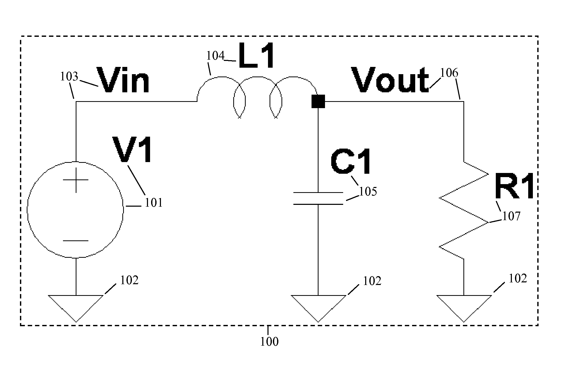
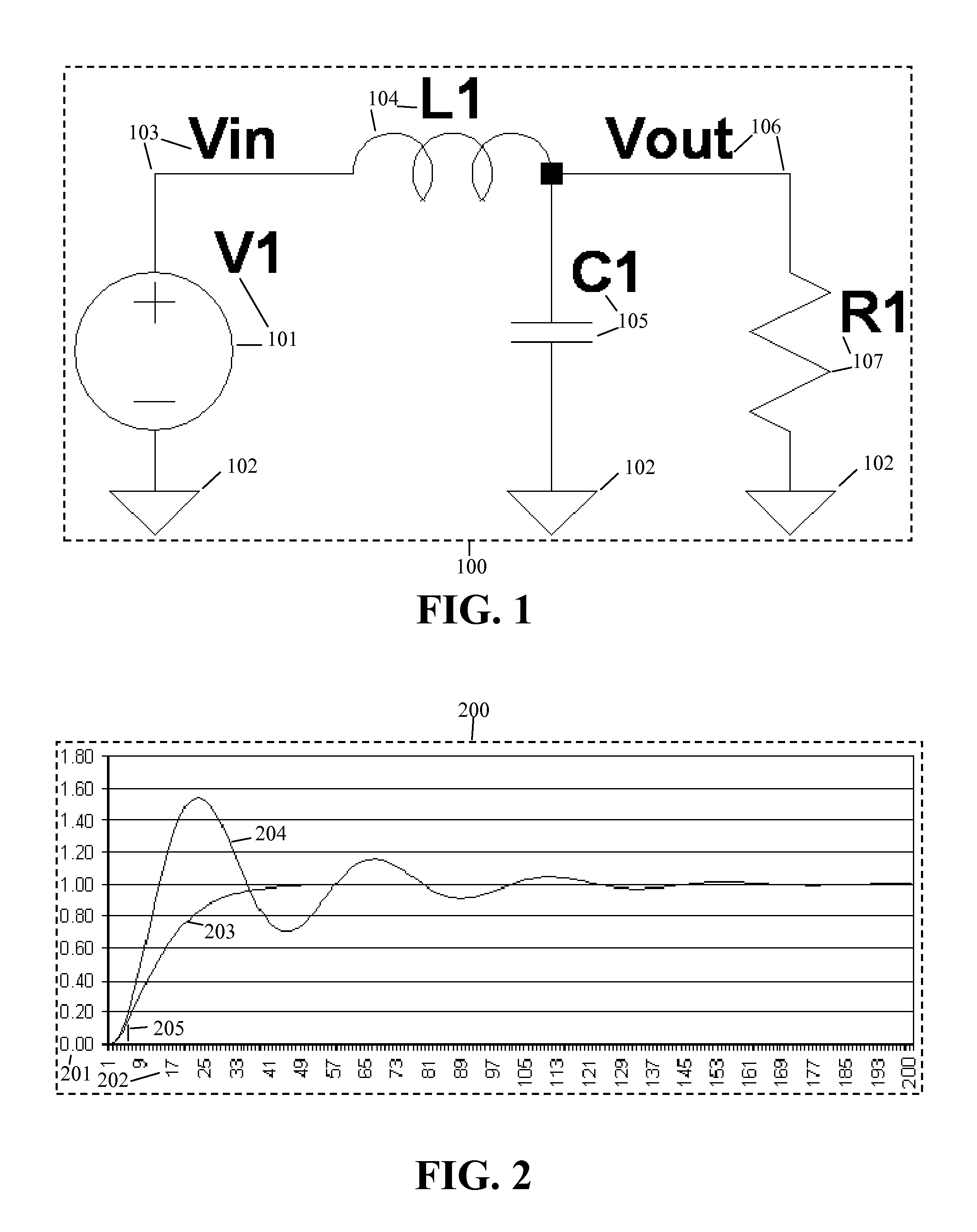
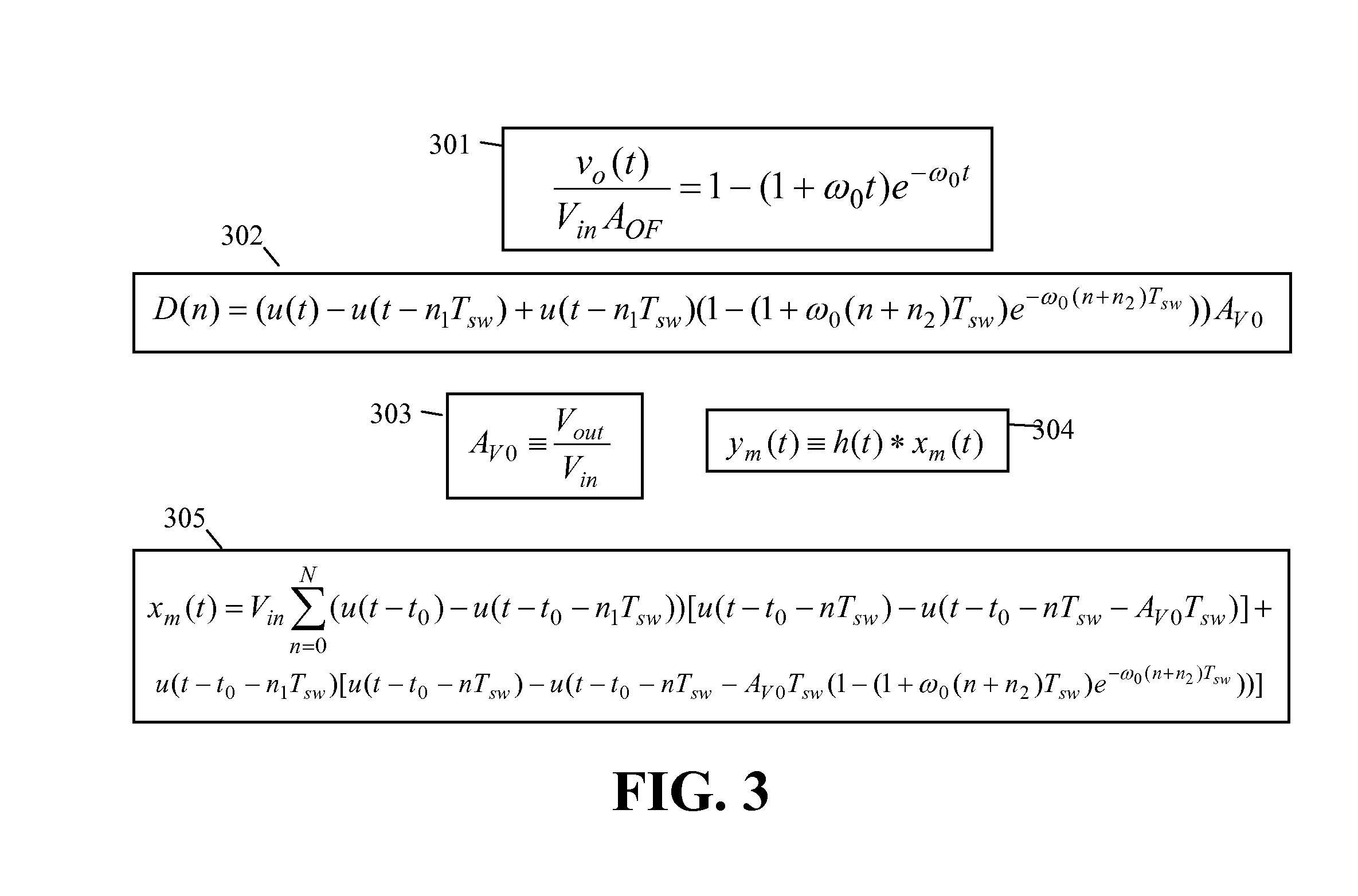
[0031]The present invention pertains to a control system and algorithm for generating a near critical damped step response using pulse width modulation techniques in an inherently under damped system. The following description contains specific information pertaining to various embodiments and implementations of the invention. One skilled in the art will recognize that one may practice the present invention in a manner different from that specifically depicted in the present specification. Furthermore, the present specification has omitted some of the specific details of the present invention in order to not obscure the invention. A person of ordinary skills in the art would have knowledge of the specific details not described in the present specification. Obviously, one may omit or only partially implement some features of the present invention and remain well within the scope and spirit of the present invention.

[0032]The following drawings and their accompanying detailed descripti...


PUM


Abstract

A digital circuit implementing pulse width modulation controls power delivered in what one can model as a second order or higher order system. An exemplary control plant could embody a step-down switch mode power supply providing a precise sequence of voltages or currents to any of a variety of loads such as the core voltage of a semiconductor unique compared to its input / output ring voltage. An algorithm produces a specific sequence of pulses of varying width such that the voltage or current delivered to the load from the system plant closely resembles a critical damped step response. The specific pulse width modulation sequence controls a plant that provides a near critical damped step response in one embodiment without a feed-forward or feedback loop physically embodied in the control system thereby reducing the parts cost or control semiconductor production yield cost while enhancing noise immunity and long term reliability of the control system. The specific algorithm exhibits tolerance to variations of twenty percent or greater in output load or ten percent or greater in control plant element parameters thus maintaining near critical damped step response characteristics when actual parameter values deviate from initial estimates.

Description

BACKGROUND OF THE INVENTION[0001]1. Field of the Invention[0002]The present invention is generally in the field of control systems. More specifically, the present invention is in the field of use of pulse width modulation in a control system. This specification herein exemplifies the present invention by an open loop, and subsequently, a closed loop digital power supply embodying voltage or current regulation.[0003]2. Background Art[0004]For more than half a century, control system engineers have implemented pulse width modulation schemes for driving a regulated voltage or current from a control plant. Control system engineers of ordinary skill in the art have long since designed digital open loop pulse width modulation control schemes to power loads that do not require precise voltage or current regulation. These digital open loop pulse width modulation control systems generally have powered loads such as DC motors, or heating elements, or other inductive and / or resistive loads whi...

Claims


Application Information

Patent Timeline
Patent Type & Authority Applications(United States)
IPC IPC(8): H03K7/08
CPCG06F1/025Y02B70/1425H03K7/08H02M3/156Y02B70/10G05B11/28G05B5/01
Inventor GIZARA, ANDREW ROMAN
Owner IPOWER HLDG
Why Eureka
Eureka Blog
Learn More