Catalyst for Light Olefins and Lpg in Fludized Catalytic Units

a technology of fludized catalytic units and light olefins, which is applied in the direction of catalyst activation/preparation, physical/chemical process catalysts, hydrocarbon oil treatment products, etc., to achieve the effect of enhancing olefin yield

Active Publication Date: 2008-04-24
WR GRACE & CO CONN
View PDF39 Cites 44 Cited by
  • Summary
  • Abstract
  • Description
  • Claims
  • Application Information

AI Technical Summary

Benefits of technology

[0039] Without being bound by any particular theory, it has been discovered that by carefully selecting the amount of rare earth in exchanged Y-type zeolites and using high surface area matrix, one can increase the content of Y-type zeolite and pentasil above those amounts typically found in standard FCC catalyst, and thereby then, enhancing olefin yields beyond those catalysts available currently.

Problems solved by technology

% poses a new challenge for existing catalyst technology, as these yields typically cannot be achieved with currently available ZSM-5 additives.

Method used


Image

  • Catalyst for Light Olefins and Lpg in Fludized Catalytic Units
  • Catalyst for Light Olefins and Lpg in Fludized Catalytic Units
  • Catalyst for Light Olefins and Lpg in Fludized Catalytic Units

Examples


example 1

The Invention

[0123] Catalyst A, containing 45% USY zeolite, 33% clay and 22% by weight silica sol binder was prepared as follows. An aqueous slurry of USY (4 wt % Na2O) was blended with Natka clay and then milled in a Drais mill. Silica sol binder was added to the milled slurry and mixed well before spray drying in a Bowen spray dryer. The silica sol binder was prepared from sodium silicate and acid alum. The resulting spray dried product was washed with ammonium sulfate solution, followed by water to give a catalyst with a Na2O level of less than 0.45 wt %. The product was steam deactivated in a fluidized bed reactor for 4 hours at 816° C. in a 100% steam at atmospheric pressure. The deactivated catalyst is designated Catalyst A-Stm.

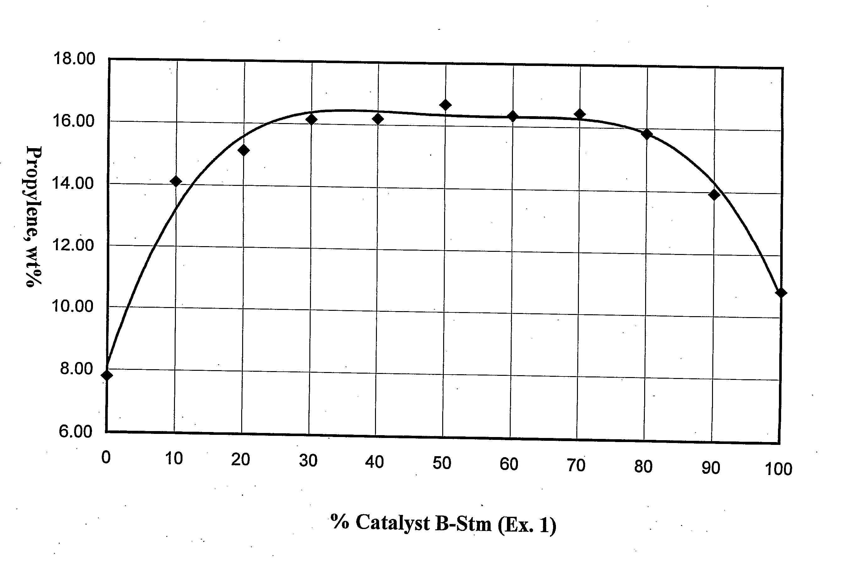
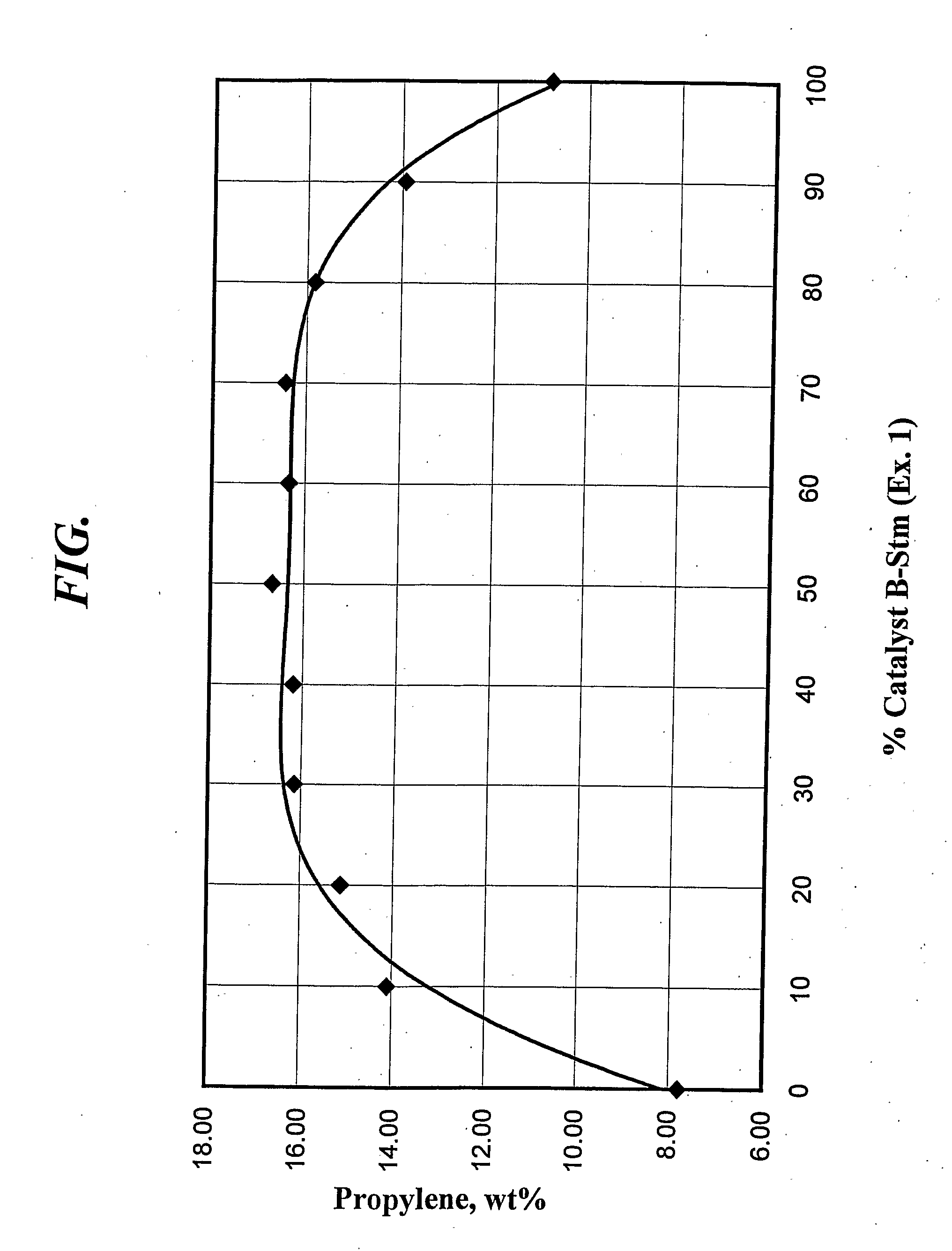
[0124] Catalyst B, containing 40% ZSM-5, was prepared as described in US 2002 / 0049133. The catalyst was steam deactivated in a fluidized bed reactor for 4 hours at 816° C. in a 100% steam atmosphere. The deactivated catalyst is designated Catalyst B-S...

example 2

Matrix Surface Area

[0128] Catalyst C, containing 55% USY, 5% Boehmite alumina and 20% alumina sol binder, 2% RE2O3 on zeolite and remainder clay, was prepared as follows. An aqueous slurry of 9.8 kg USY zeolite (1% Na2O, 34% solids) was blended with 367 g of rare earth salt solution (27% RE2O3), 300 g (dry basis) of a particulate Boehmite alumina, 1200 g Natka clay (dry basis) and 5.2 kg of aluminum hydrochlorol (23% Al2O3). The slurry was mixed well and then milled in a Drais mill. The milled catalyst slurry was spray dried in a Bowen spray drier. The spray-dried product was calcined for 40 minutes at 400° C. The calcined product was then washed using conventional techniques to lower the Na2O level. The catalyst was steamed in a fluidized bed reactor for 4 hours at 816° C. in a 100% steam atmosphere. The deactivated Catalyst C was combined in a 1:1 ratio with Catalyst B-Stm. The catalyst combination is designated Catalyst CB-Stm. The surface area of Catalyst CB-Stm is shown in Tab...

example 3

[0129] Catalyst D, containing 55% USY, 20% alumina sol binder, 5% Boehmite alumina and 2% RE2O3 on zeolite was prepared as follows. An aqueous slurry of USY (1% Na2O on zeolite) was blended with aluminum chlorohydrol, Boehmite alumina, rare earth salt, and Natka clay. The slurry was mixed well and then milled in a Drais mill. The milled catalyst slurry was spray dried in a Bowen spray drier. The spray-dried product was calcined for 40 minutes at 593° C. The catalyst was steamed in a fluidized bed reactor for 4 hours at 816° C. in a 100% steam atmosphere. The deactivated Catalyst D was combined in a 1:1 ratio with Catalyst B-Stm. The catalyst combination is designated Catalyst DB-Stm. The surface area of Catalyst DB-Stm is shown in Table 4.


PUM

PropertyMeasurementUnit
weight ratioaaaaaaaaaa
weight percentaaaaaaaaaa

Abstract

A catalyst composition comprising at least about 10% by weight pentasil, at least about 12% by weight Y-type zeolite at a pentasil to Y zeolite ratio of at least 0.25, and wherein the pentasil and Y zeolite comprise at least about thirty-five percent of the catalyst have been shown to optimize light olefin yields and LPG from FCC processes. Embodiments having matrix surface areas greater than 25 m2/g, phosphorous and rare earth are preferred. The compositions of this invention are particularly useful in typical fluid catalytic cracking (FCC) processes.

Description

BACKGROUND [0001] 1. Field of the Invention [0002] The invention relates to use of catalysts to enhance yields of olefins and liquefied petroleum gas (LPG) produced in a fluidized catalytic cracking (FCC) process. [0003] 2. Description of Related Art [0004] A discussion relating to use of ZSM-5-based catalysts to enhance olefin yields in FCC processes is found in U.S. Pat. No. 5,997,728. The following description of related art is based on that discussion. [0005] Catalysts used in FCC processes are in particle form, usually have an average particle size in the range of 20 to 200 microns, and circulate between a cracking reactor and a catalyst regenerator. In the reactor, hydrocarbon feed contacts hot, regenerated catalyst which vaporizes and cracks the feed at about 400° C. to 700° C., usually 500° C. to about 550° C. The cracking reaction deposits carbonaceous hydrocarbons or coke on the catalyst, thereby deactivating it. The cracked products are separated from the coked catalyst. ...

Claims


Application Information

Patent Timeline
Patent Type & Authority Applications(United States)
IPC IPC(8): B01J29/80C10G11/05
CPCB01J2229/42B01J29/088C10G2400/02B01J29/80B01J2229/20B01J37/0045B01J29/084C10G11/05C10G2300/202B01J29/40B01J35/0006C10G2300/301C10G2400/20C10G11/18C10G2400/28C10G2300/4025C10G2300/4093C10G11/182B01J21/12B01J29/08B01J27/14
Inventor CHENG, WU CHENGKRISHNAMOORTHY, MEENAKSHI SUNDARAMKUMAR, RANJITZHAO, XINJINZIEBARTH, MICHAEL SCOTT
Owner WR GRACE & CO CONN
Why Eureka
Try Eureka