Steam generation apparatus and method

a technology of steam generator and steam generator, which is applied in the direction of steam generation using hot heat carriers, and working-up pitch/asphalt/bitumen by distillation. it can solve the problems of reducing the quality of steam, reducing the efficiency of cold ambient temperature, and reducing the viscosity of produced materials. , to achieve the effect of reducing the amount of extraneous, reducing th

Inactive Publication Date: 2008-04-24
ACS ENG TECH
View PDF5 Cites 10 Cited by
  • Summary
  • Abstract
  • Description
  • Claims
  • Application Information

AI Technical Summary

Benefits of technology

[0016]In accordance with another aspect of the present invention, lighter portions of the products of the refinery are added to produced bitumen, asphaltines or heavy oil as diluent for reducing the produced material's viscosity in order to facilitate a reduction in the amount of extraneously provided diluent required to meet pipeline specifications for transport, and which in another embodiment also provides for the use of ge

Problems solved by technology

Exceeding 80% quality renders a project uneconomical, largely due to water treatment costs.
Conversely, lower than 80% quality steam introduces inefficiencies to the process utilized for heavy oil or bitumen recovery and, hence, is also undesirable from a cost-effectiveness perspective.
Typically the quality of the steam will degrade as heat exchange surfaces foul over the run time of the equipment.
(a) failure to maintain 80% quality steam (or such other quality of steam as required or desired) at the outlet of the boiler—often lower quality steam is generated; and
(b) cost of fuel, typically natural gas, to fire the boilers used for steam generation (plus the cost of associated pipeline construction and maintenance to bring the natural gas or other fuel to the boiler).
In addition, problems typical fo

Method used


Image

  • Steam generation apparatus and method
  • Steam generation apparatus and method
  • Steam generation apparatus and method

Examples


Embodiment Construction

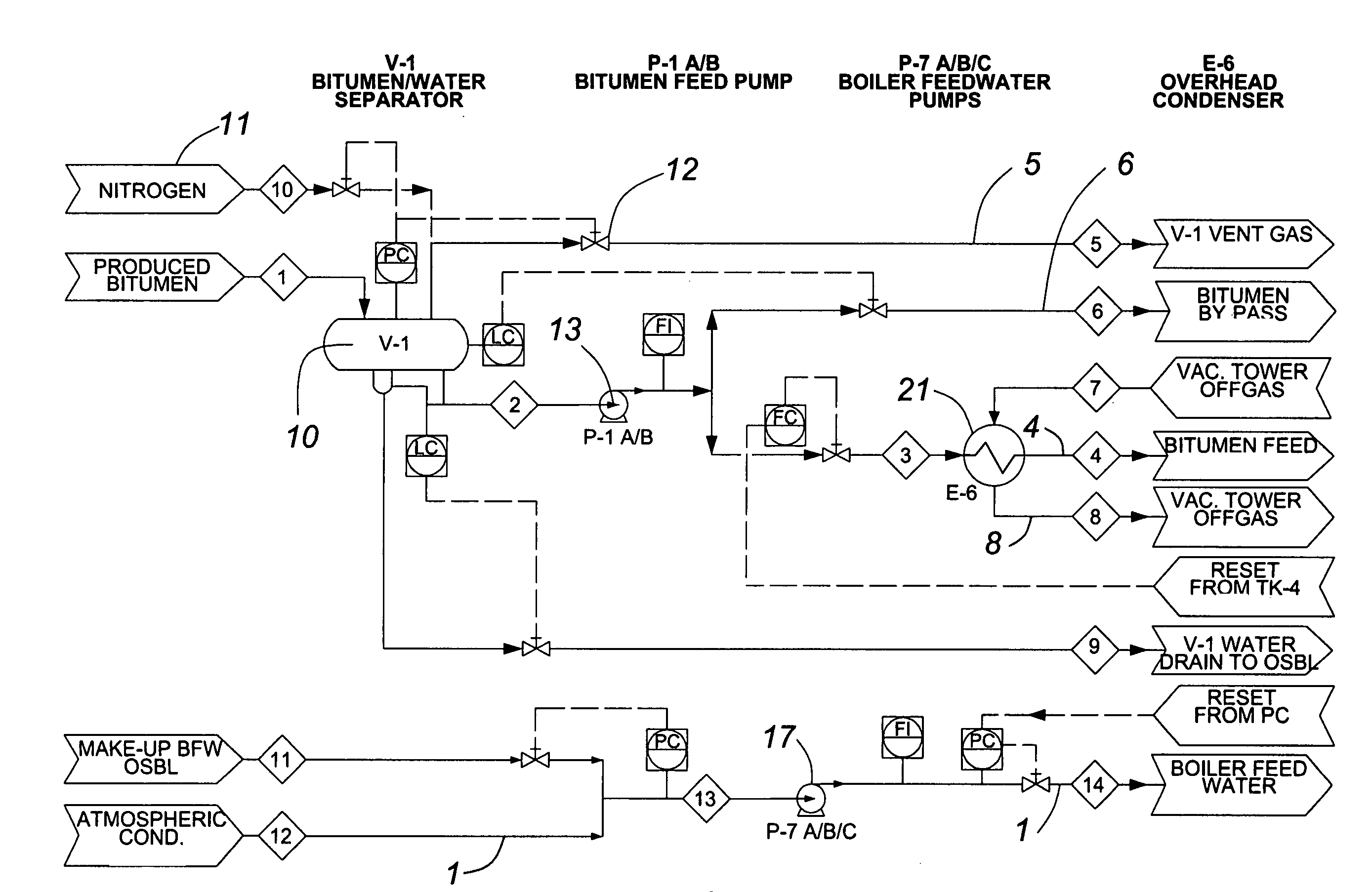
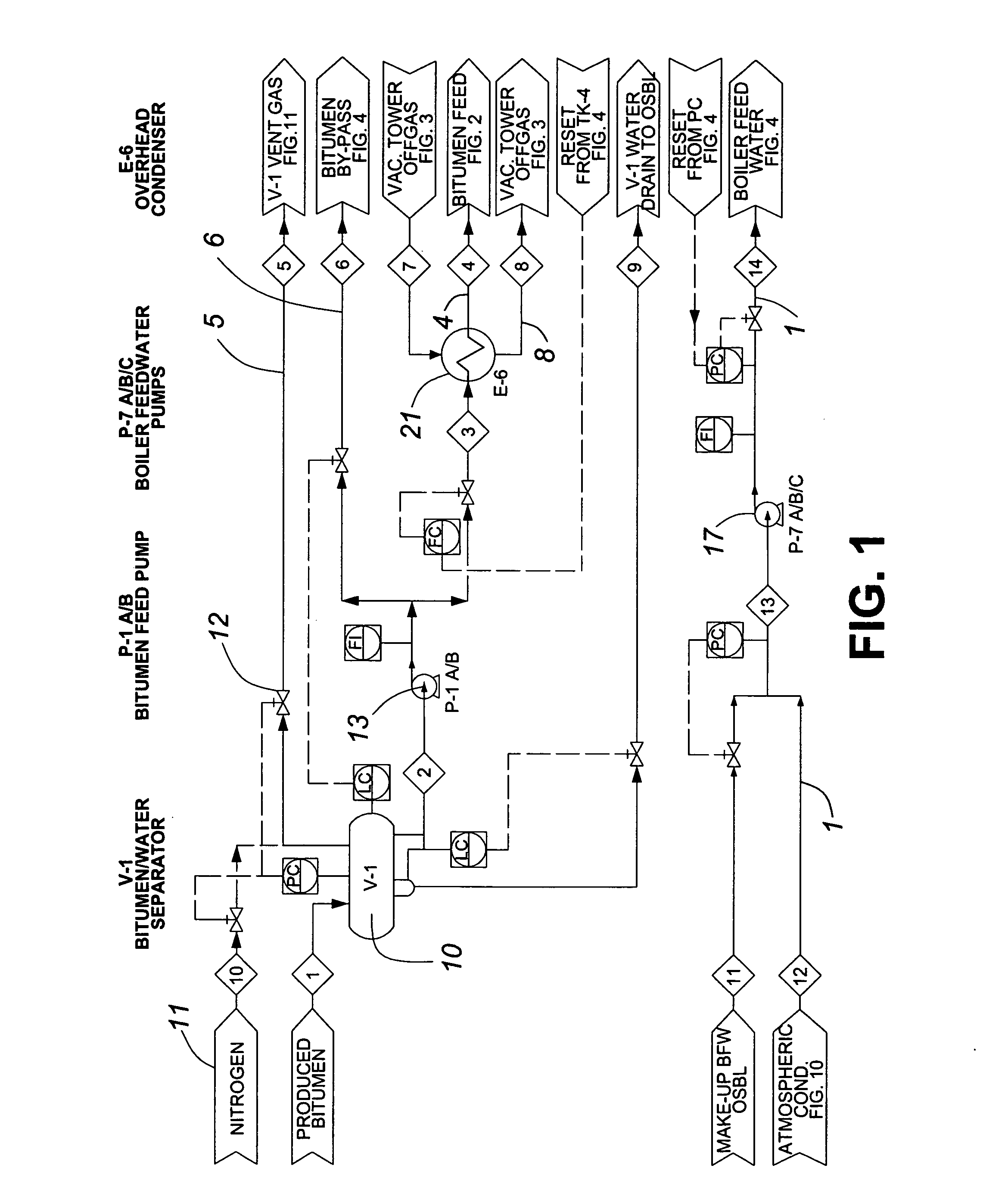
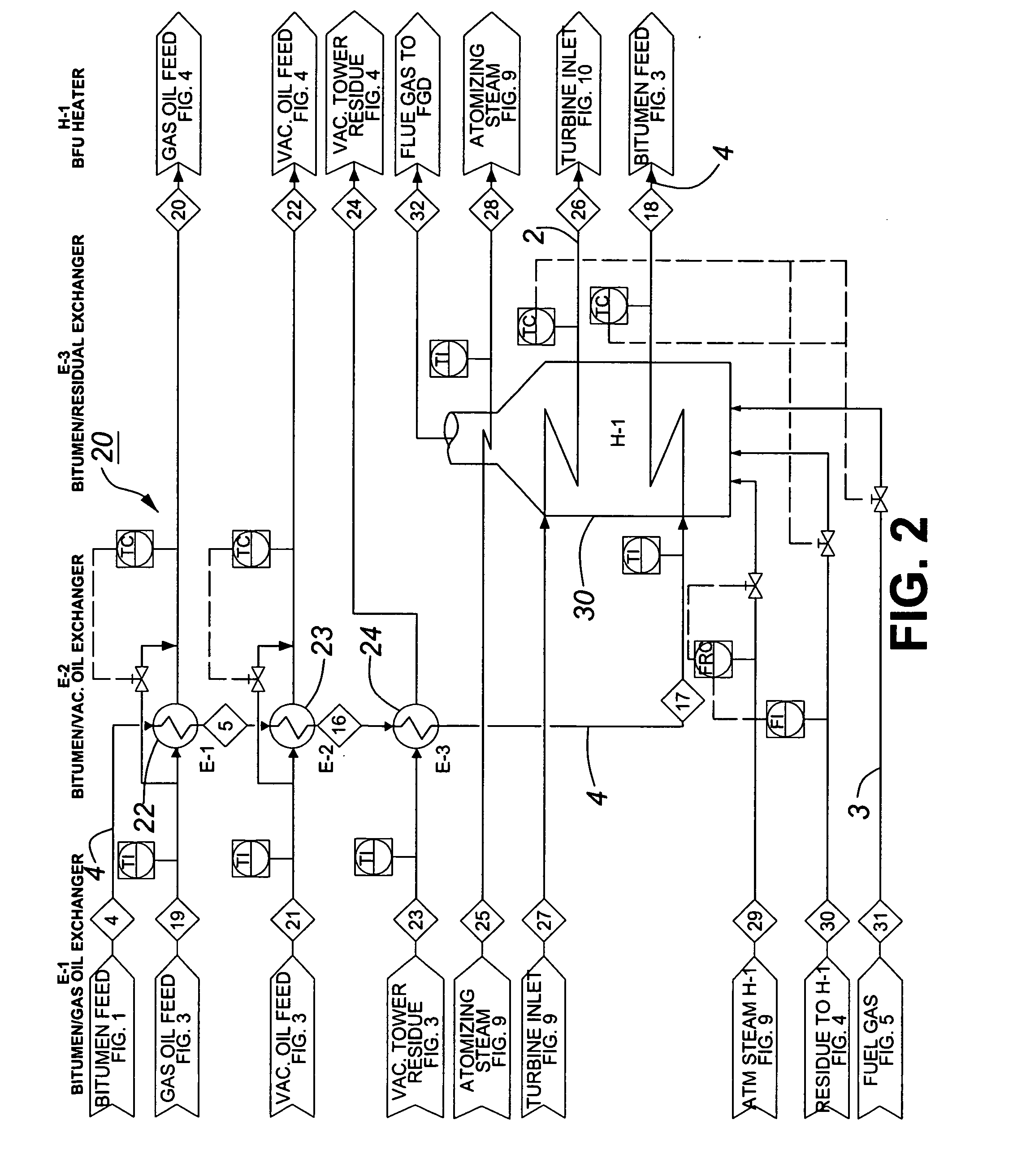
[0029]The present invention generally comprises bitumen feed surge vessel, heat exchanger system, a heater, a vacuum tower, an off-gas compressor, product tankage, and flow control system, a steam generation system, a power generation system, and a flare system.

[0030]It is to be understood that the description following is an embodiment of the present invention, is descriptive and exemplary but no limiting, and that there are substitutions and replacements of certain process equipment or process steps which will be apparent to those skilled in the art, and which are claimed as part of this invention.

Bitumen Feed Surge Drum

[0031]Referring to FIG. 1, in this embodiment bitumen is dewatered utilizing standard SAGD equipment prior to entering through a feed surge drum 10 through supply line 1. The feed surge drum 10 has an internal baffle (not shown) and a boot for water separation. The boot on the drum 10 will be controlled with an interface level control. The drum 10 is purged with ni...


PUM


Abstract

The present invention provides for steam generation replacing natural gas with a selected refined product of a feedstock of bitumen, asphaltines or heavy oil using locally produced surplus bitumen, asphaltine or heavy oil, separating the asphaltines and other components of the feedstock for use in providing a liquid fuel for steam generation. The lighter products from the separation equipment not used for liquid fuel may be blended into the produced bitumen, asphaltines or heavy oil, to increase its API gravity and reduce the diluent required for transportation. This technology may be employed in open pit mining operations for the generation of steam and power. The refined components of the feedstock used to provide liquid fuel are selected to optimize energy output balancing planned energy demand against the value of the components of the feedstock used.

Description

FIELD OF THE INVENTION[0001]The present invention relates to a steam generator and in particular to a steam generation apparatus and method replacing natural gas as fuel with a selected portion of bitumen, asphaltines or heavy oil optimised for desired energy or steam production.BACKGROUND OF THE INVENTION[0002]Steam is often used in industrial processes. For example, steam can be used for heat exchange, as a power source for driving turbines, etc.[0003]In the petroleum industry, for example, a particular application is for the generation of steam for the recovery of bitumen or heavy oil. A common process utilized for the in situ recovery of heavy oil or bitumen is to inject steam underground pursuant to which the viscosity of bitumen or heavy oil is decreased such that it flows and is capable of being pumped to the surface. For this, steam generation apparatus commonly called steam injection boilers (“SIB”) are used to generate steam of the required / desired quality or quantities. T...

Claims


Application Information

Patent Timeline
IPC IPC(8): C10G27/04
CPCF22B1/18C10L1/04
Inventor SARKAR, SUJIT K.MITCHELL, DAVID J.
Owner ACS ENG TECH
Why Eureka
Try Eureka