Method and apparatus for controlling charging operations for battery

a charging operation and battery technology, applied in the direction of secondary cell servicing/maintenance, speed sensing governors, instruments, etc., can solve the problems of increased useless fuel consumption, battery is likely to be affected by noise, and the conventional methods mentioned above have been developed without considering engine efficiency or power generation efficiency of a vehicle generator. , to achieve the effect of reducing the processing load of an external control unit for engine control

Active Publication Date: 2008-04-24
DENSO CORP
View PDF11 Cites 45 Cited by
  • Summary
  • Abstract
  • Description
  • Claims
  • Application Information

AI Technical Summary

Benefits of technology

[0015] Thus, processing load of an external control unit for engine control can be mitigated. Also, performing power generation control based on the target SOC independently of the engine control, appropriate power generation control can be performed even when the processing load for the engine control is large (even when the engine is in high-speed rotation).

Problems solved by technology

The conventional methods mentioned above have been developed without considering engine efficiency or power generation efficiency of a vehicle generator.
Therefore, there has been a problem that an operation in a state where these efficiencies are low, has increased useless fuel consumption.
This has raised a problem that the battery is likely to be affected by noise.
When this controller has been realized by using an engine control microcomputer, there has been a problem that high engine speed may impose a heavy processing load on the microcomputer in the engine control and that appropriate power generation control may not possibly be performed.

Method used


Image

  • Method and apparatus for controlling charging operations for battery
  • Method and apparatus for controlling charging operations for battery
  • Method and apparatus for controlling charging operations for battery

Examples


Embodiment Construction

[0024] With reference to the accompanying drawings, hereinafter will now be described a charge control system according to embodiments of the present invention.

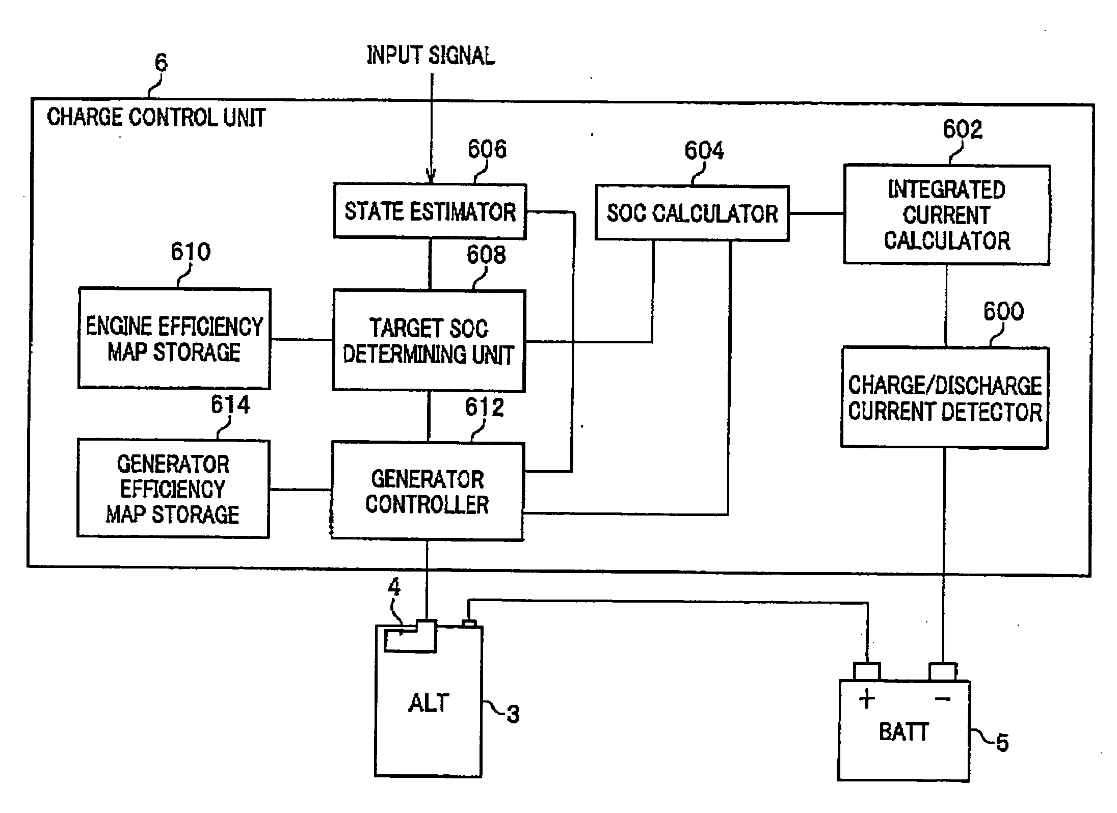
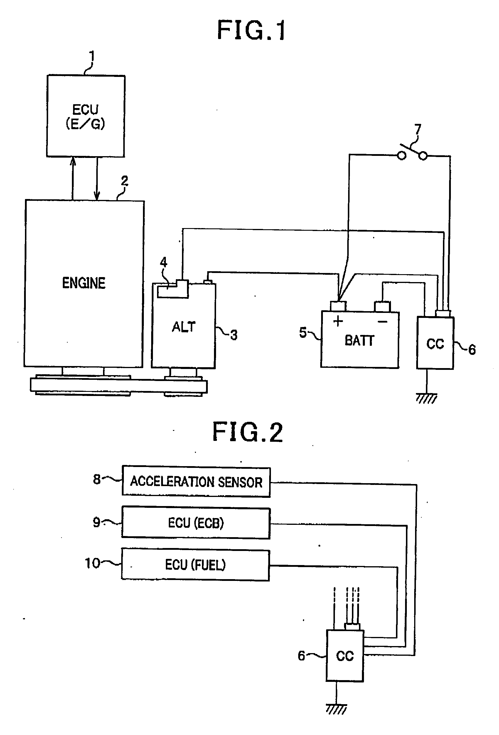
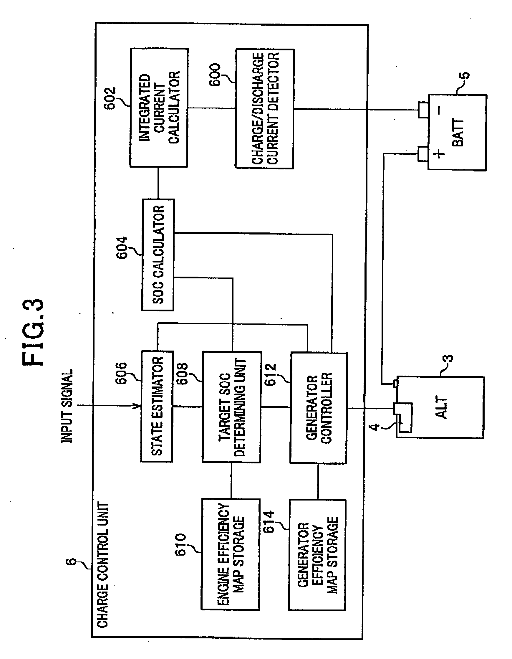
[0025]FIG. 1 is a schematic diagram illustrating a general configuration of a charge system in which a charge control system according to an embodiment of the present invention is incorporated. The charge system shown in FIG. 1 includes an ECU (electronic control unit) 1 for an engine (E / G), an internal combustion engine 2, an on-vehicle generator (i.e., alternator: ALT) 3 (hereinafter referred to as a “generator 3”), a battery (BATT) 5, a charge control unit (CC) 6 and a key switch 7.

[0026] The ECU (E / G) 1 is an electronic control unit serving as an external control unit for controlling the engine 2, while monitoring the rotating conditions and other drive conditions of the engine 2. The generator 3 generates power by being rotated and driven by the engine 2 through a belt to supply charging power for the battery 5 and ope...


PUM

PropertyMeasurementUnit
adjustment voltageaaaaaaaaaa
output voltageaaaaaaaaaa
voltageaaaaaaaaaa

Abstract

An apparatus controls a state of charge (SOC) of a battery mounted on a vehicle provided with an internal combustion engine driving a generator mounted on the vehicle. The generator charges the battery. In the apparatus, a setting unit sets a target value directed to controlling the SOC of the battery such that the target value is higher as an efficiency of the internal combustion engine depending on the number of rotations of the engine is higher. A determining unit determines whether the vehicle is in a decelerated state. A controlling unit controls a state of rotation of the generator to enable the generator i) to perform regeneration when it is determined that the vehicle is in the decelerated state and ii) to perform generation to enable the SOC of the battery to be the target value when it is determined that the vehicle is not in the decelerated state.

Description

CROSS-REFERENCE TO RELATED APPLICATION [0001] This application is based on and claims the benefit of priority from earlier Japanese Patent Application No. 2006-288225 filed Oct. 24, 2006, the description of which is incorporated herein by reference. BACKGROUND OF THE INVENTION [0002] 1. Technical Field of the Invention [0003] The present invention relates to a method and an apparatus for controlling charging operations for battery, which operations are conducted by a vehicle generator loaded, for example, on a passenger car or a truck. [0004] 2. Related Art [0005] As known well, a battery mounted in vehicles need to be adjusted on its operating conditions. Such an example is disclosed in Japanese Patent Laid-Open Publication No. 2003-209935, in which there is disclosed a method for controlling adjustment voltage so that an integrated value of charge / discharge current of an on-vehicle battery will be zeroed, with the aid of the battery-condition (voltage, current and temperature) det...

Claims


Application Information

Patent Timeline
Patent Type & Authority Applications(United States)
IPC IPC(8): H02P9/02G01R31/36H01M10/44H02J7/16
CPCG01R31/3606H01M10/48Y02T10/92H02P9/02H02J7/1446G01R31/382Y02E60/10
Inventor MAEDA, SYUNICHIASADA, TADATOSHI
Owner DENSO CORP
Why Eureka
Try Eureka