Range sensor using structured light intensity

a sensor and light intensity technology, applied in the field of precision measurement instruments, can solve problems such as contributing to the complexity of position calculations, and achieve the effects of reducing the sensitivity of the signal to the optical power of the source and to temperature fluctuations, and low cos

Inactive Publication Date: 2008-05-01
MITUTOYO CORP
View PDF3 Cites 6 Cited by
  • Summary
  • Abstract
  • Description
  • Claims
  • Application Information

AI Technical Summary

Benefits of technology

[0012]In accordance with another aspect of the invention, a second light source may also be utilized, wherein in one embodiment the second light source may be directed in an opposite direction to the first light source, and a second reflective surface and second detector may be utilized in combination with the second light source. In one embodiment, the distance between the first and second reflective surfaces is fixed (e.g. as attached to a common frame), which moves relative to the fixed positions of the first and second light sensors. By utilizing this balanced detector approach, the signal response is made to vary linearly with the distance to the first surface, and the sensitivity of the signal to the optical power of the source and to temperature fluctuations is reduced. In one embodiment, the second light source may comprise a back facet of the first light source (e.g. both facets of a laser diode are used as outputs).
[0013]It will be appreciated that the present invention provides a method and configuration for a simple, inexpensive position sensor with a linear signal response to position. In one embodiment, the scale-less sensor makes use of engineered micro-lens array technologies or engineering diffractive optical element (DOE) technologies to create the flat-top line profile, either of which may be made using volume manufacturing options to produce parts at low cost.

Problems solved by technology

One of the disadvantages of the prior art systems described above is that the distance from the sensor to the reflecting surface is calculated in accordance with the inverse square attenuation of the light, which contributes to the complexity of the position calculations.

Method used


Image

  • Range sensor using structured light intensity
  • Range sensor using structured light intensity
  • Range sensor using structured light intensity

Examples


Embodiment Construction

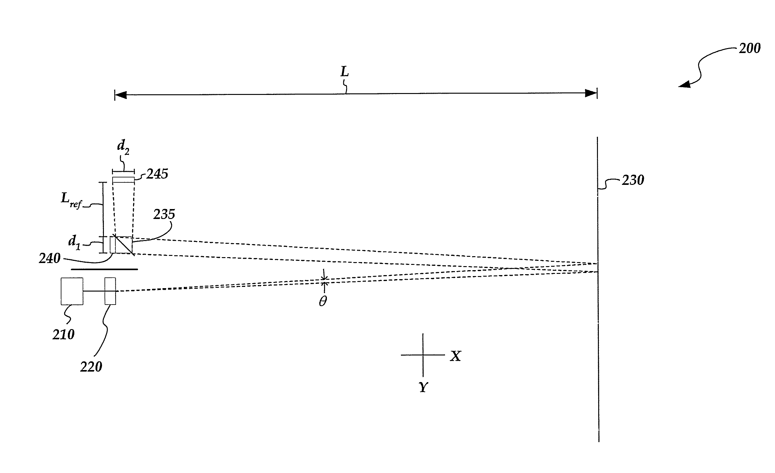
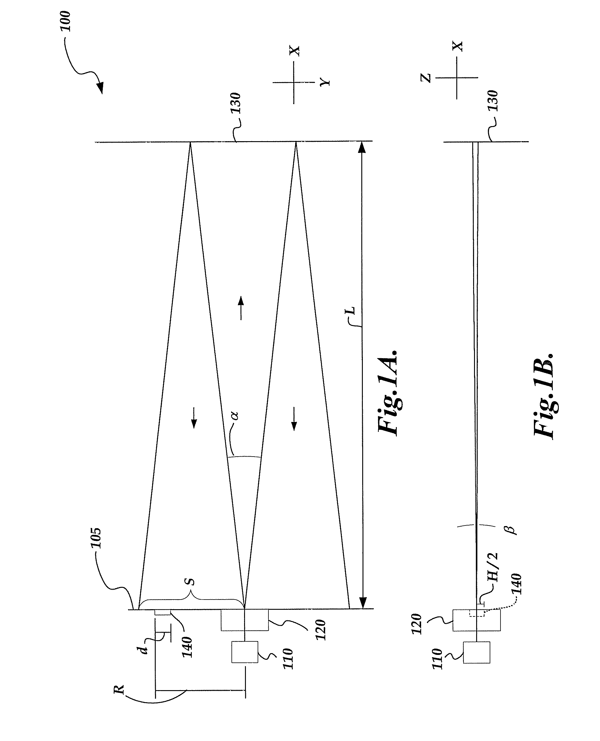
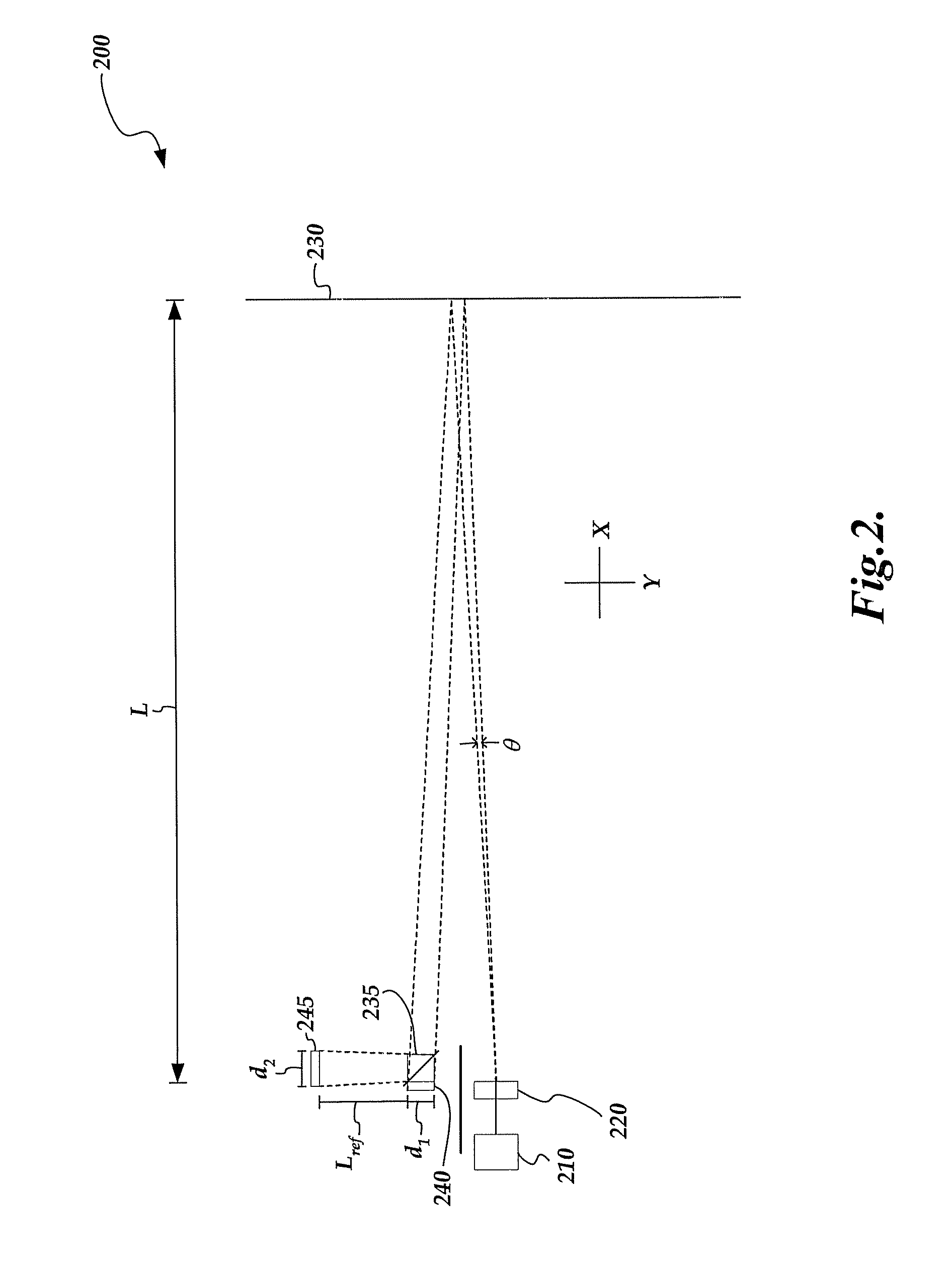
[0019]FIGS. 1A and 1B are diagrams of top and side views, respectively, of one exemplary embodiment of a range sensor 100 using structured light intensity for determining displacement measurements in accordance with the present invention. As shown in FIG. 1A, a source 110, beam structuring element 120 and detector 140 are shown proximate to a detector plane 105. In one embodiment, the source 110, beam structuring element 120 and detector 140 are fixed to a body (not shown) of the sensor 100. The source 110 may in certain embodiments be a light source such as a laser, VCSEL, LED, etc. In one embodiment, the beam structuring element 120 may comprise a lens and a line generator, in which case the light from the source 110 is collimated by the lens and is directed through the line generator. In one embodiment, the beam from the beam structuring element 120 is reflected by a mirror 130. After the beam is reflected by the mirror 130, a portion of the reflected light is received by the det...


PUM


Abstract

A range sensor using structured light intensity for determining displacement measurements. A micro-lens array or diffractive optical element inputs light from a light source and outputs a flattop intensity pattern in a diverging light stripe. By using a diverging light stripe, the response of the system to a change in position is made to vary approximately proportionally to the inverse of a distance from a reflecting surface to the source of the diverging light stripe. A dual detector approach may be utilized to eliminate the sensitivity of measurement signal with respect to variations in the optical power the light source, as well as other potential variations.

Description

FIELD OF THE INVENTION[0001]The invention relates generally to precision measurement instruments, and more particularly to a range sensor using structured light intensity for determining displacement measurements.BACKGROUND OF THE INVENTION[0002]Various movement or position transducers involve placing a transmitter and a receiver in various geometric configurations to measure movement between two members of the transducer. Certain transducers of this type have used the inverse square attenuation of light reflected from a diffuse surface to calculate the distance from a sensor readhead to the reflecting surface. As an example, U.S. Pat. No. 4,865,443 (the '443 patent) discloses an optical displacement sensor wherein light transmitted from an optical fiber or the like is directed onto a surface whose distance from the sensor is to be measured. The intensity of the reflected light is angle dependent, but within a sufficiently small solid angle the intensity falls off as the inverse squ...

Claims


Application Information

Patent Timeline
Patent Type & Authority Applications(United States)
IPC IPC(8): G01C3/08G01B11/14
CPCG01B11/026G01S17/46G01C3/08
Inventor SESKO, DAVID WILLIAM
Owner MITUTOYO CORP
Why Eureka
Try Eureka