System and method for generating intense laser light from laser diode arrays

a laser diode array and laser light technology, applied in the field of lasers, can solve the problems of insufficient output from one laser diode stripe for many applications in terms of power level and beam quality, and the disadvantage of semiconductor laser diodes, and achieve the effects of efficient focusing, high brightness, and effective combination of outpu

a laser diode array and laser light technology, applied in the field of lasers, can solve the problems of insufficient output from one laser diode stripe for many applications in terms of power level and beam quality, and the disadvantage of semiconductor laser diodes, and achieve the effects of efficient focusing, high brightness, and effective combination of outpu

US20080101429A1Active Publication Date: 2008-05-01MIND MELTERS

Image

  • System and method for generating intense laser light from laser diode arrays
  • System and method for generating intense laser light from laser diode arrays
  • System and method for generating intense laser light from laser diode arrays

Examples


Embodiment Construction

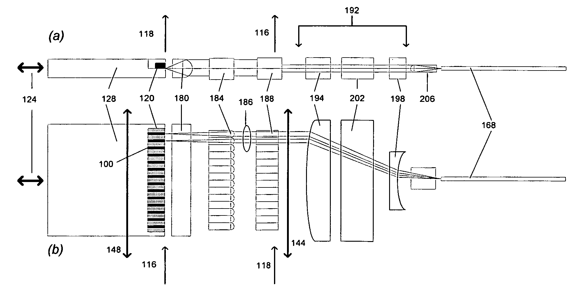
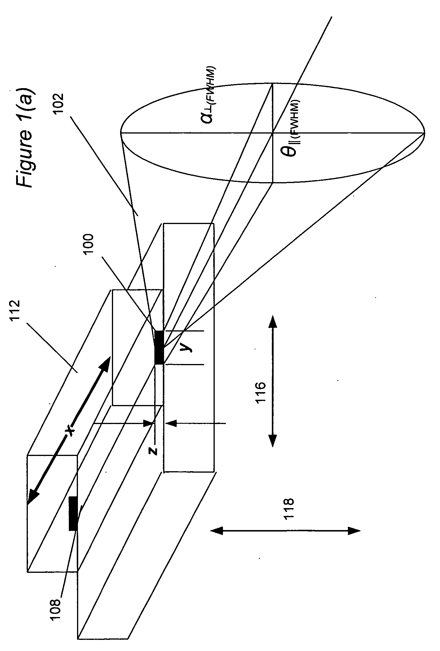
[0023]Turning now to the drawings, prior to describing the system and method of the invention, the structure of a laser diode and the properties of its output light is described first to facilitate an understanding and appreciation of the approach of the invention. As explained below, the invention is especially advantageous for combining the output beams from two-dimensional arrays of laser diodes to form an intense high-quality fiber-coupled beam. Nevertheless, the present invention is not limited to laser diodes, and can be applied to other forms of laser elements with a diffraction-limited small lasing area, including those that may be developed in the future.

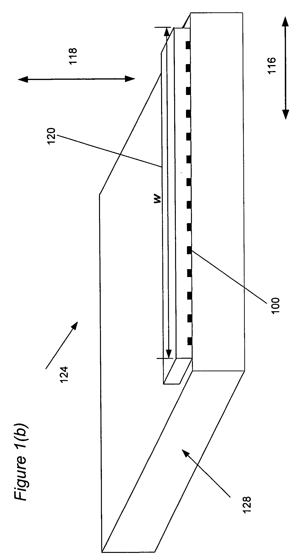
[0024]FIG. 1 (a) shows the typical geometry of a single broad area semiconductor laser diode 104 grown by epitaxial deposition. This device is characterized by an emitting or active region 100 of width y and thickness z and length x. This expitaxially grown and photolithographically defined region can be constructed in many...


PUM


Abstract

Laser modules using two-dimensional laser diode arrays are combined to provide an intense laser beam. The laser diodes in a two-dimensional array are formed into rows and columns, and an optical assembly images light generated by laser diodes in a column into an optical fiber. The laser light outputs of the laser modules are combined by a spectral combiner into an optical fiber to form an intense laser beam.

Description

TECHNICAL FIELD[0001]The present invention relates to lasers, and more particular to optical configurations to effectively couple the outputs of a plurality of individual laser elements, such as laser diodes, into optical fibers to provide high efficiency transmission of power through the optical fiber.BACKGROUND OF THE INVENTION[0002]The compact size and high efficiency of semiconductor laser diodes make them the ideal candidates for applications requiring concentrated and spectrally pure laser light sources. Applications such as optical storage, low end printing and telecommunications that once used many different types of laser sources, now only use semiconductor laser diode sources once these diode laser sources with the required characteristics were successfully developed. The primary reason that semiconductor laser diodes have these very useful characteristics is that the excited or pumped laser area can be made very small through the use of semiconductor fabrication technique...

Claims


Application Information

Patent Timeline
01 May 2008
Publication
US20080101429A1
IPC
H01S5/00
CPC
G02B6/4296; G02B27/0961; G02B27/0966; G02B19/0014; H01S5/405; G02B19/0057; G02B27/283; H01S5/4012
Inventors
SIPES, DONALD L.