
Signal Processing Method, Signal Processing Device, and Signal Processing Program

a signal processing and signal processing technology, applied in the direction of frequency response correction, instruments, electrical transducers, etc., can solve the problems of increasing computational complexity, increasing computational complexity, and increasing the required memory size, so as to reduce computational complexity, accurate control of coefficient update, and high performance of removing echoes

Inactive Publication Date: 2008-05-01
NEC CORP
View PDF1 Cites 90 Cited by
  • Summary
  • Abstract
  • Description
  • Claims
  • Application Information

AI Technical Summary

Benefits of technology

[0064]A first effect is that high performance of removing echoes is attained. This is because accurate control of coefficient update can be achieved by estimating a noise getting into a microphone signal, and detecting a double talk using information corrected with the estimated noise.
[0065]A second effect is that computational complexity is reduced. This is because complex matrix or vector calculation is not used in double-talk detection.
[0066]A third effect is that influence of erroneous detection is reduced. This is because a reliability coefficient as expressed by a continuous value between zero and one is used in double-talk detection.

Problems solved by technology

However, it is not easy to select an appropriate threshold in advance for all cases.
Thus, a plurality of adaptive filters are required, thus increasing computational complexity.
The third conventional technique requires a plurality of sets of adaptive filter coefficients, thus raising a problem that a required memory size is increased.
Therefore, this technique requires a plurality of microphones and is not applicable to a system comprising a single microphone.
Since in a general acoustic system, however, an echo path gain is not known, difficulty is encountered in selecting a detection threshold.
Therefore, difficulty is encountered in selecting a detection threshold.
Since the analysis parameter for a reference signal and a microphone signal should be found, there arises a problem that computational complexity is increased.
The ninth conventional technique conducts double-talk detection using the frequency of saturation and the power of an error, and difficulty is encountered in selecting a threshold for saturation.
Thus, detection performance is dependent upon the margin, which is difficult to determine.
Both these conventional techniques employ two microphones, and are not applicable to a system comprising a single microphone.
The value of the determinant, however, is variable depending upon an environment, resulting in difficulty in selecting the threshold.

Method used


Image

  • Signal Processing Method, Signal Processing Device, and Signal Processing Program
  • Signal Processing Method, Signal Processing Device, and Signal Processing Program
  • Signal Processing Method, Signal Processing Device, and Signal Processing Program

Examples


embodiment 1

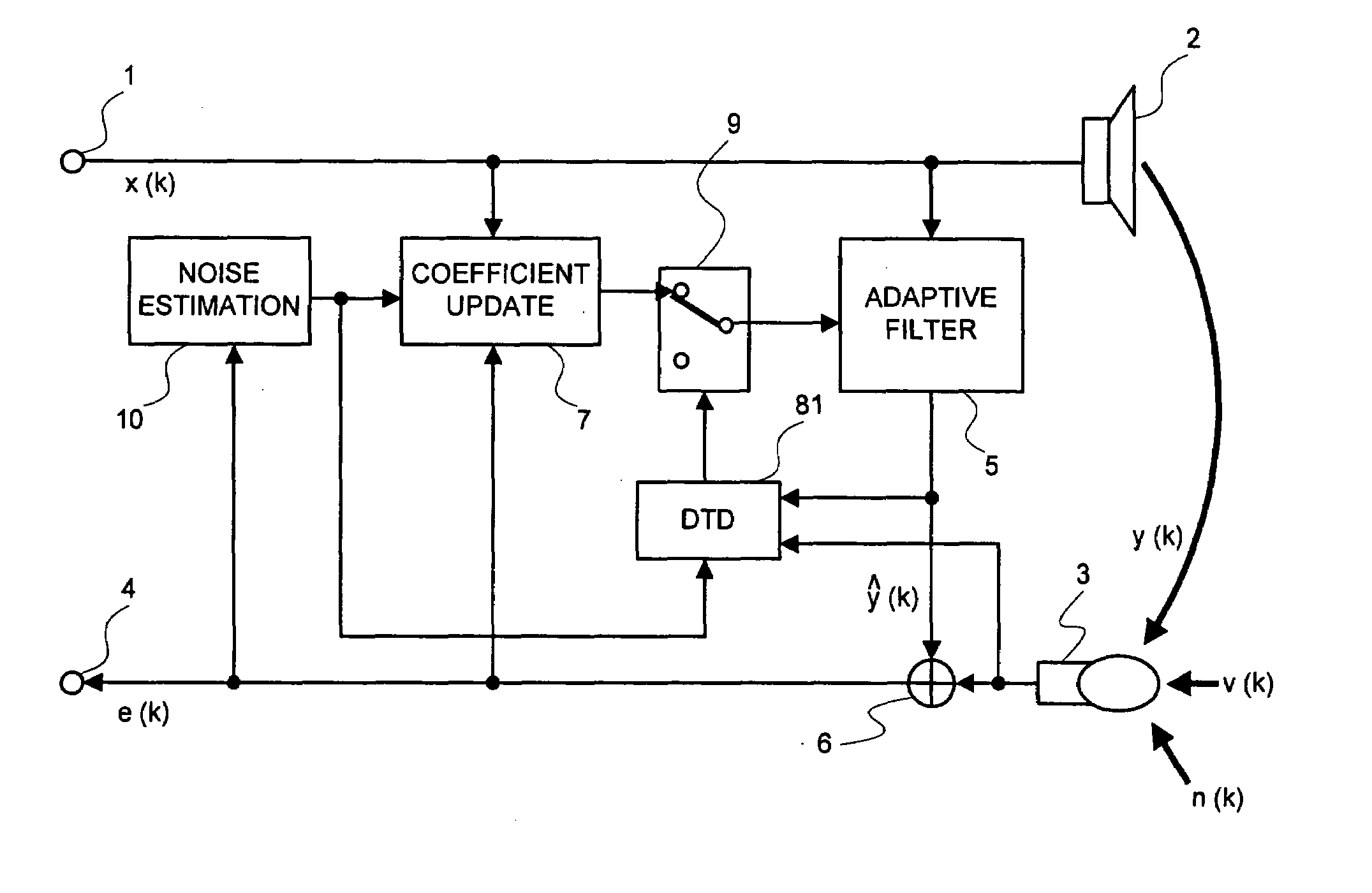
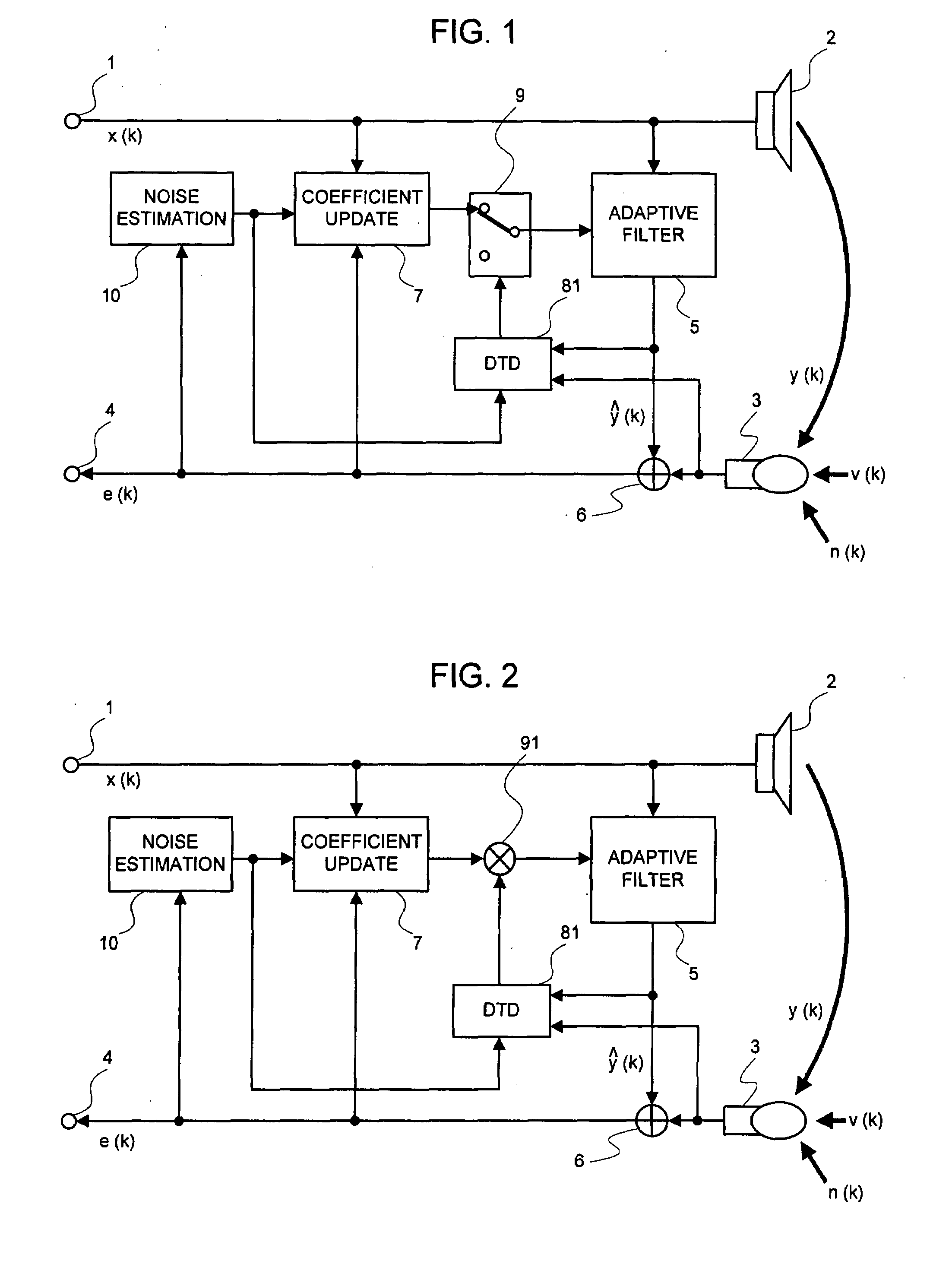
[0097]The double-talk detecting circuit 81 is supplied with a microphone signal m(k) and a pseudo echo y(k) hat. A procedure to detect a double talk using these signals will be given below:

[0098]Applying rxm=Rxxh to EQ. (9) gives EQ. (12):

[Equation5]ξ=hTRxxhσm2.(12)

[0099]Using an approximation of EQ. (10), i.e., h W(k), and paying attention to the fact that E[hTX(k)]=E[y(k) hat], the following equation is obtained:

[Equation6]ξ(k)=E[y^(k)2]σm2.(13)

In this equation, ξ is time-varying and therefore it is given as a function of k. The calculation of EQ. (13) consists of one multiplicative operation for a numerator in the radical sign, and one multiplicative operation for a denominator therein. In practice, σm2 is the average power of the microphone signal m(k), and is determined as:

[Equation7]σm2(k)=∑j=0M-1m2(k-j).(14)

Since EQ. (14) is a moving average of m2(k), it can be calculated for a past value by an additive operation of m2(k) and a subtractive operation of m2(k-M) in practice. Th...

embodiment 2

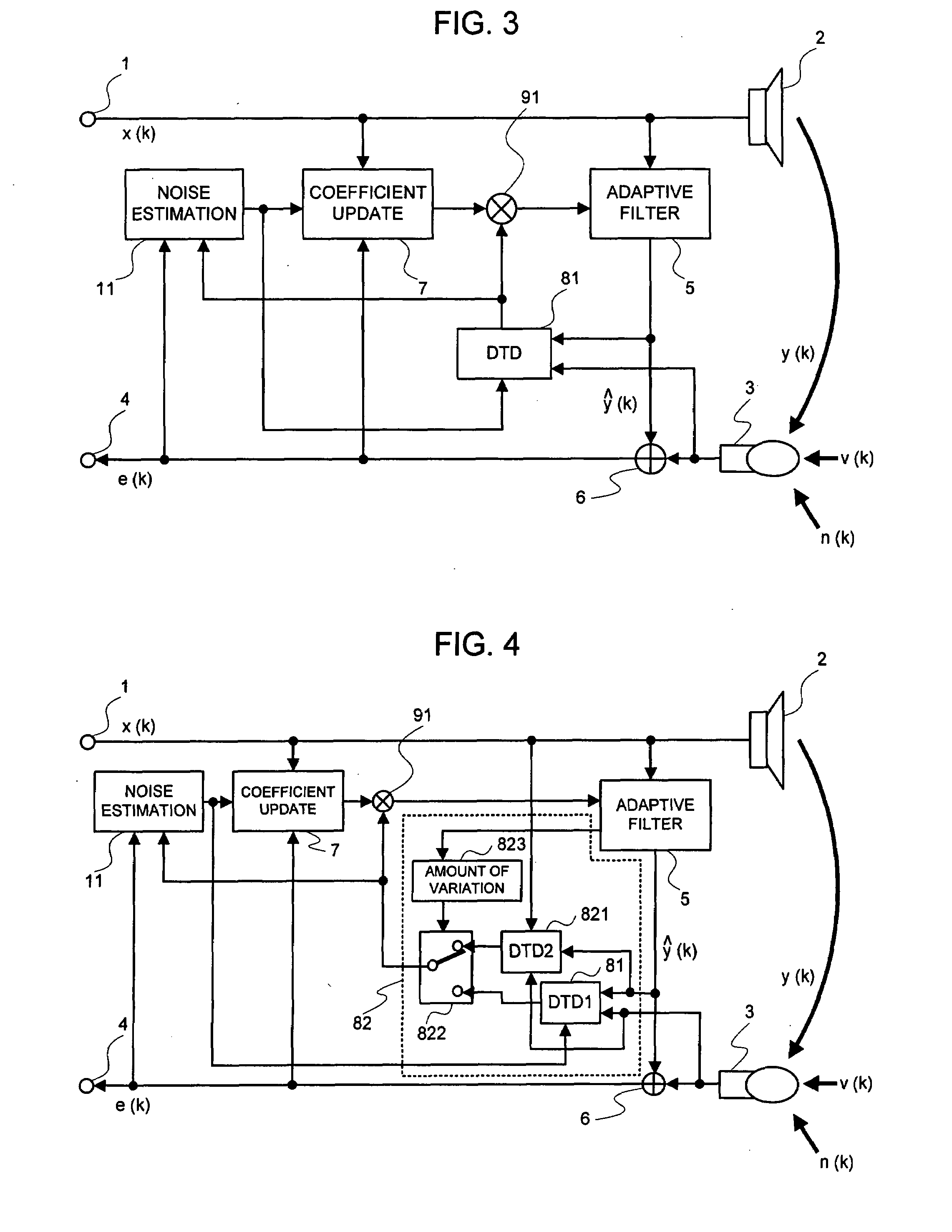
[0116]In an embodiment 2, a time-varying threshold is applied to ξ(k). From EQ. (26), the value of ξ(k) in a double talk is approximately dependent upon a ratio between the power of a near-end signal and the power of an echo. Thus, if the power of a near-end signal and the power of an echo can be estimated, the value of ξ(k) in a double talk can be determined. The power of an echo can be sequentially determined by approximating it with the power of a pseudo echo. The power of a near-end signal can be calculated similarly to EQ. (21) as:

v2(k)hat=Ave[e2(k)].  (27)

The calculation of Ave[·] can be achieved using the moving average as given by EQ. (14) or (15), or a linear leaky integration represented by:

v2(k+1)hat=v2(k)hat+(1−δv)·e2(k),  (28)

where δv is a time constant for averaging. For δv, adaptive control similar to that for δn may be used.

[0117]As can be clearly seen from EQ. (23), EQ. (28) is calculated to update v2(k) hat only when the residual echo and noise are substantially sm...

embodiment 3

[0119]An embodiment 3 shown in FIG. 2 comprises a multiplier 91 in place of the switch 9. The double-talk detecting circuit 81 supplies to the multiplier 91a reliability coefficient for a double talk expressed by a continuous value between zero and one. The multiplier 91 multiplies the amount of coefficient update supplied from the coefficient updating circuit 7 by the reliability coefficient, and then transmits a result to the adaptive filter 5. Thus, coefficient update is made by the amount corresponding to the reliability coefficient for a double talk. This means that coefficient update is completely suspended if a double talk is confidently decided, and is made by an amount corresponding to the reliability if a double talk is uncertain. Thus, performance of removing echoes is improved as compared with either-or control in which coefficient update is to be made or not.

[0120]Representing a reliability coefficient as θ(k), it can be determined by:

θ(k)={ξ(k)−ξDT(k)} / {1−ξDT(k)}.  (29...


PUM


Abstract

A signal processing device includes an adaptive filter (5), a noise estimation circuit (10), and a double talk detection circuit (81) and operates so that the double talk detection circuit (81) detects a double talk by using the estimated noise obtained by the noise estimation circuit (10). The signal processing device further includes noise estimation means and detects a double talk by using an estimated noise, a microphone signal, and pseudo-echo. An echo removal method and device detect a double talk by using a reliability coefficient expressed as continuous values between 0 and 1. By using continuous values instead of two values 0 and 1, it is possible to reduce the affect of a detection error.

Description

TECHNICAL FIELD[0001]The present invention relates to a signal processing method, a signal processing device, and a signal processing program, and particularly to a signal processing method, a signal processing device, and a signal processing program capable of providing high performance of removing interfering signals in an environment having mixed sounds superposed with interfering signals such as echoes or noises.BACKGROUND ART[0002]Several kinds of interfering signals superposed over a target signal include a line echo generated in a two-wire-to-four-wire converter circuit in a communication line, an acoustic echo generated by acoustic coupling between a speaker for reproducing acoustic signals and a microphone, a background noise or voice of other people getting into a microphone for catching a target signal.[0003]In a two-wire-to-four-wire converter circuit, there is a known technique for removing an echo leaking from a transmitter to a receiver on the four-wire side, such as ...

Claims


Application Information

Patent Timeline
IPC IPC(8): H04B3/20H04B15/00
CPCH04M9/082H04R3/04H04R3/002H04B3/234G10K11/002H04R2410/05G10L21/0216G10L2021/02082G10L2021/02163
Inventor SUGIYAMA, AKIHIKO
Owner NEC CORP
Learn More