Degradable whipstock apparatus and method of use

a whipstock and defleadable technology, applied in water installations, directional drilling, borehole/well accessories, etc., can solve the problems of reducing flow area and adding cos

Inactive Publication Date: 2008-05-08
SCHLUMBERGER TECH CORP
View PDF47 Cites 208 Cited by
  • Summary
  • Abstract
  • Description
  • Claims
  • Application Information

AI Technical Summary

Benefits of technology

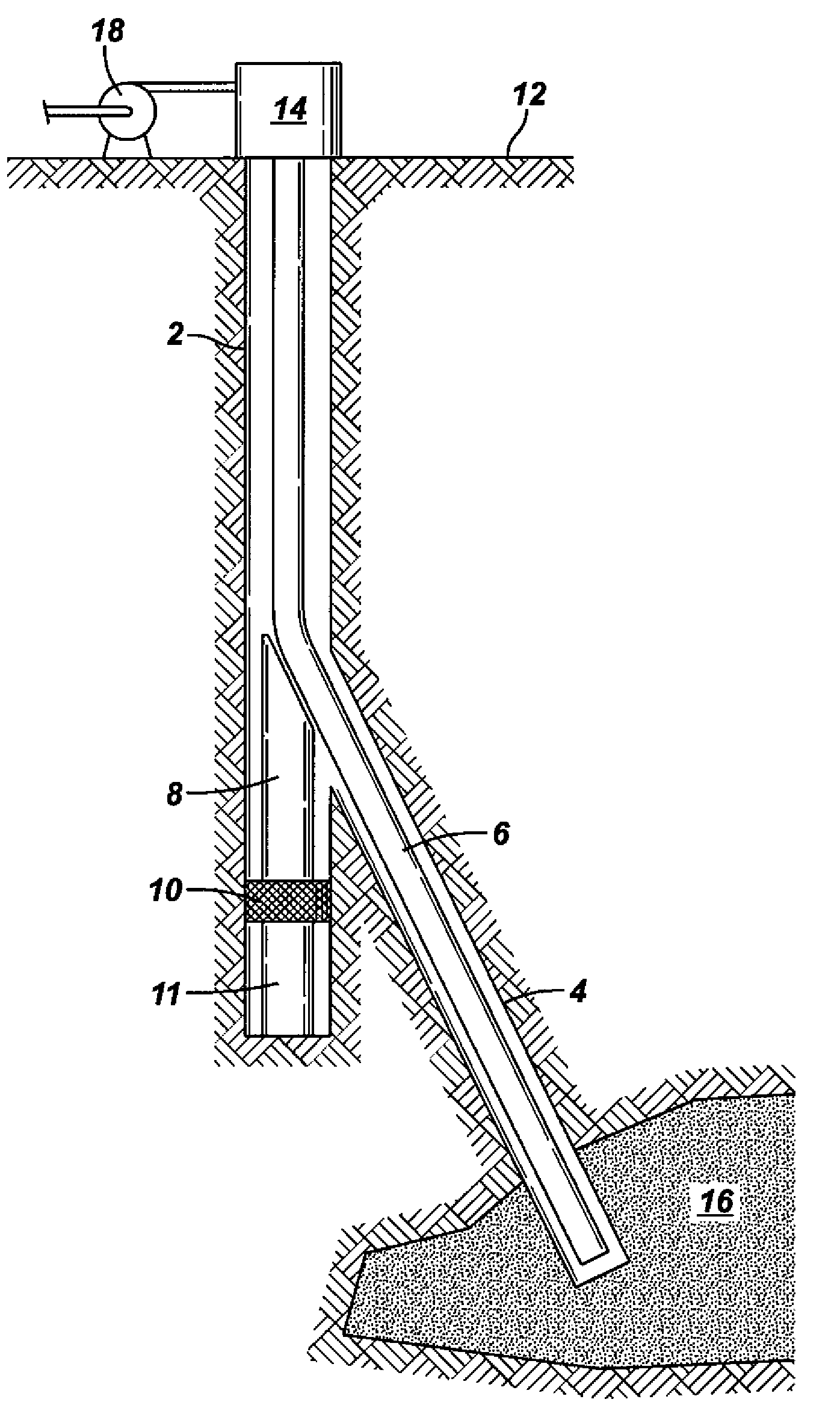
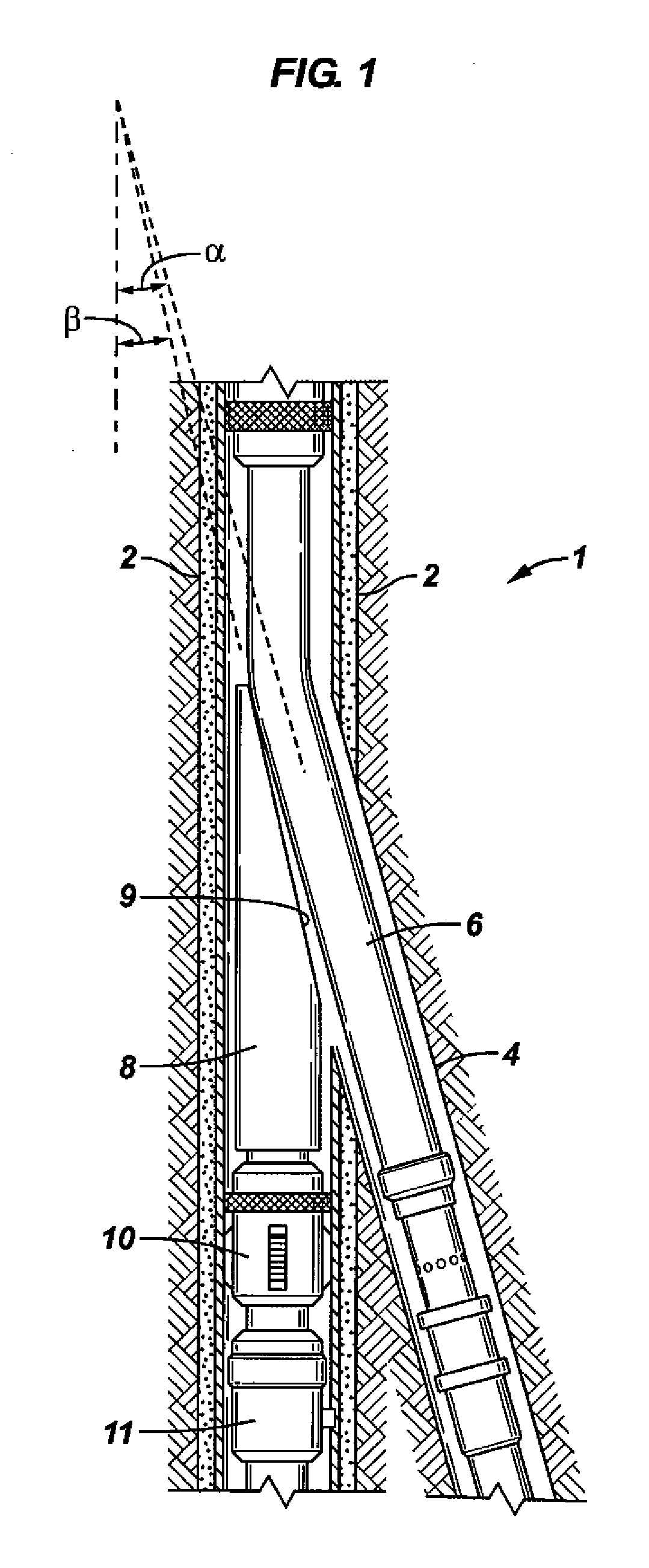
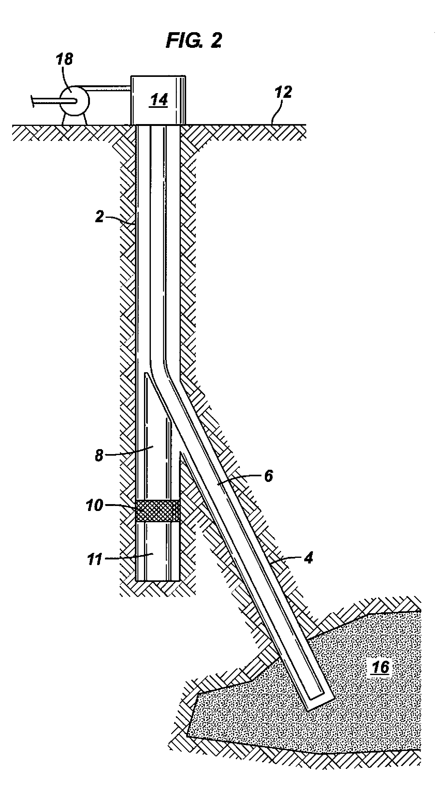
[0009] In accordance with the present invention, whipstock and deflector apparatus comprising a user-controlled degradable composition, and methods of using same are described that reduce or overcome limitations of previously known whipstock and deflector apparatus and methods. By combining reactive metals and their properties with other relatively reactive or non-reactive supplemental components, including in certain embodiments alloying elements, the inventive apparatus (for example, but not limited to alloys, composites, and smart combinations of materials) are formed and may be utilized to advantage in oilfield operations. Deflectors and whipstocks of the invention may be applied to a multitude of oilfield operations, including, but not limited to, deflecting drill bits and other equipment from a first wellbore to a lateral wellbore. As one example of an apparatus and method of use of the invention, a whipstock comprising a highly reactive composition consisting essentially of a degradable component, for example dissolving within minutes, may be protected by a coating that specifically becomes dysfunctional at or about reservoir temperature. Such whipstock and deflector embodiments of the invention, though simplistically described in this example, offer new advantages to temporarily deflect equipment into separate laterals and zones of a reservoir. The whipstock or deflector apparatus, once allowed to warm up for instance to the reservoir temperature, first fails for instance by the melting or fracture of its coating, among other mechanisms, before fully degrading by dissolution, disintegration, or both. When the element becomes dysfunctional, the element may not yet be entirely degraded and therefore may either fall or float to a new position but without obstructing well operation. In this and other embodiments of the invention, no intervention is therefore required to remove the element after its useful life of diverting equipment is completed.

Problems solved by technology

These devices must be retrieved with a separate trip in the well, which is added cost.
However, the presence of the devices in the main bore means reduced flow area.

Method used


Image

  • Degradable whipstock apparatus and method of use
  • Degradable whipstock apparatus and method of use
  • Degradable whipstock apparatus and method of use

Examples


examples and experimental

RESULTS

[0084]FIG. 4 is a photograph of a simple experiment on a sub-sized laboratory sample to first demonstrate the validity of the claims. In FIG. 4 is pictured a extruded calcium rod that was simplistically cast inside a 54Bi-30In-16Sn eutectic alloy for coating purposes, and fully immersed in distilled (neutral-pH) water while subjected to a slow heating from ambient temperature. Once the water temperature exceeded the melting temperature of the coating (i.e. of the eutectic alloy), the coating melted away, exposing the calcium metal to the corrosive fluid (distilled water) and thus triggering its rapid degradation by dissolution. In FIG. 4, the bubbling that may seen in the liquid above the composition is evidence of the release of diatomic hydrogen; i.e. the only gas that may be produced from a simple metallic composition like calcium in water. As demonstrated, a reactive metal such as calcium and a temporary protective coating made for instance of a low-melting alloy may cons...


PUM

PropertyMeasurementUnit
anglesaaaaaaaaaa
anglesaaaaaaaaaa
anglesaaaaaaaaaa

Abstract

Whipstocks and deflectors comprising a degradable composition, and methods of using same are described. In one embodiment the degradable composition consists essentially of one or more reactive metals in major proportion, and one or more alloying elements in minor proportion, with the provisos that the composition is high-strength, controllably reactive, and degradable under defined conditions. Methods of using degradable whipstocks in oilfield operations are also described. This abstract allows a searcher or other reader to quickly ascertain the subject matter of the disclosure. It will not be used to interpret or limit the scope or meaning of the claims. 37 C.F.R. 1.72(b).

Description

CROSS-REFERENCE TO RELATED APPLICATIONS [0001] The present application claims priority under 35 U.S.C. § 119(e) to U.S. Provisional Application Ser. Nos. 60 / 771,627, filed Feb. 9, 2006, and 60 / 746,097 filed May 1, 2006, both of which are incorporated by reference herein in their entirety, and also claims priority under 35 U.S.C. § 120 to co-pending U.S. non-provisional application Ser. No. 11 / 427,233, filed Jun. 28, 2006, which is also incorporated herein by reference.BACKGROUND OF THE INVENTION [0002] 1. Field of Invention [0003] The present invention relates generally to the field of oilfield exploration, production, and testing, and more specifically to deflector apparatus commonly known as whipstocks comprising degradable compositions, and methods of using same. [0004] 2. Related Art [0005] Existing structural compositions, that is materials and combinations of materials, have been developed to sustain elevated loads (forces, stresses, and pressures) at useful ranges of temperat...

Claims


Application Information

Patent Timeline
Patent Type & Authority Applications(United States)
IPC IPC(8): E21B29/00
CPCC22C1/0408C22C12/00C22C13/00C22C13/02C22C21/00E21B7/061C22C21/06C22C21/10C22C28/00C22C30/04C22C30/06C22C21/003
Inventor JORDAN, ANTHONY L.KAMATH, RAGHURAMNIXON, VANCE E.MARYA, MANUEL P.
Owner SCHLUMBERGER TECH CORP
Why Eureka
Try Eureka