Pulse power generator using semiconductor switch

a technology of semiconductor switch and power generator, which is applied in the direction of pulse train generator, pulse technique, apparatus without intermediate ac conversion, etc., can solve the problems of inflexible adjustment of pulse width, noise generation, limitation in increasing pulse repetition rate, etc., and achieve the effect of improving the lifespan of the generator and its elements

Inactive Publication Date: 2008-05-08
KOREA ELECTROTECH RES INST
View PDF1 Cites 43 Cited by
  • Summary
  • Abstract
  • Description
  • Claims
  • Application Information

AI Technical Summary

Benefits of technology

[0019]Accordingly, the present invention has been made in an effort to solve the aforementioned problems occurring in the prior art, and it is an object of the present invention to provide a pulse power generator using a semiconductor switch, which solves problems associated with synchronization even while utilizing the semiconductor switch having a permanent lifespan to thereby improve the lifespan of the generator and its elements, enable its miniaturization and make it possible to diversely control a high-voltage pulse output finally.
[0020]Particularly, another object of the present invention is to provide a pulse power generator using a semiconductor switch, which addresses and solves a difficulty in driving the semiconductor switch in series, i.e., the problems related to synchronization and insulation of a driving power supply, and includes a circuit which can cope with the generation of arc and short circuit to thereby significantly improve element protecting performance and stability of the pulse power generator.

Problems solved by technology

A conventional high-voltage pulse generating circuit embraces lots of problems in terms of lifespan of the switch, variation in the pulse width, increase in the operating frequency, adjustment of the pulse voltage, need for a high-voltage DC power supply and the like.
However, the type employing the spark gaps or the vacuum-tube switch encounters shortcomings in that its lifespan is short, the adjustment of a pulse width is not flexible and very difficult, there is a limitation in increasing a pulse repetition rate and a high-voltage DC power supply circuit is needed.
Also, the type employing the pulse transformer entails demerits in that it is difficult to achieve an ultra fast rise time of a pulse due to the inductance of the transformer, the circuit is complicated since a reset circuit must be installed additionally due to the magnetic saturation of a transformer core, a noise is generated and an increase of the pulse width is difficult.
Especially, the Marx generator has several demerits in that a maximum pulse repetition rate (pulse frequency) is restricted, the arbitrary adjustment of a pulse width is impossible, and the spark gap switches have a great limitation in terms of lifespan due to abrasion generated each time a spark occurs as being mechanical discharge switches.
In addition, a short circuit occurs in a load, it is impossible to restrict a short circuit current.
Further, the Marx generator has problems in that the smaller the number of stages being connected is, the higher the voltage each stage must endure becomes so that a withstanding voltage of each switch is raised, and in that when the withstanding voltage of each stage is alternatively lowered, the number of stages to be connected increases so as to obtain a necessary voltage.
But such a conventional Marx generator still has a risk that its reliability may be deteriorated due to strict restraints on the driving of the switches simultaneously and even voltage distribution of switches.
However, in this case, when the IGBTs are turned on or off, a unbalance of the voltage is prone to occur due to a difference in driving timing.
At this time, any voltage higher than the voltage rating of IGBT may cause the IGBT to be damaged immediately.
If the turning on / off of the IGBT is not synchronized, for example, if only one IGBT from multi connected IGBTs is not synchronized with others to cause turned off earlier, the entire voltage is applied across the IGBT which is not synchronized to cause the IGBT to be damaged, which results in sequential breakages of the remaining IGBTs due to the damage of the specific IGBT.
Thus, in a high-voltage driving, one of the most difficult technologies is known as high voltage insulation of the gate power supply.
A conventional high-voltage charger, which has been used so far, entails a problem in that its entire size is greatly large.
The gate power generator, which has been developed so far, is very complicated in a structure for achieving a high-voltage insulation since it is subjected to a multi-staged voltage transformation for the sake of the high-voltage insulation.
In addition, the gate power and the gate signal are generated by means of a separate construction, respective, which leads to a complexity of the entire construction.
Besides the problems which have been known so far in regard to the Marx pulse generator of FIG. 1 and the power modulator of FIG. 2, there are additional problems in that the two types have a limitation in a pulse width (<10 μs).
Also, the generator embraces a problem in that the overall size of the apparatus is large and its operating efficiency is low.
In addition, the generator of the type employing the IGBTs and the TRs enables protection of generation of arcs, but is problematic in that circuits are complicated.

Method used


Image

  • Pulse power generator using semiconductor switch
  • Pulse power generator using semiconductor switch
  • Pulse power generator using semiconductor switch

Examples


Embodiment Construction

[0044]Reference will now be made in detail to the preferred embodiment of the present invention, examples of which are illustrated in the drawings attached hereinafter, wherein like reference numerals refer to like elements throughout. The embodiments are described below so as to explain the present invention by referring to the figures.

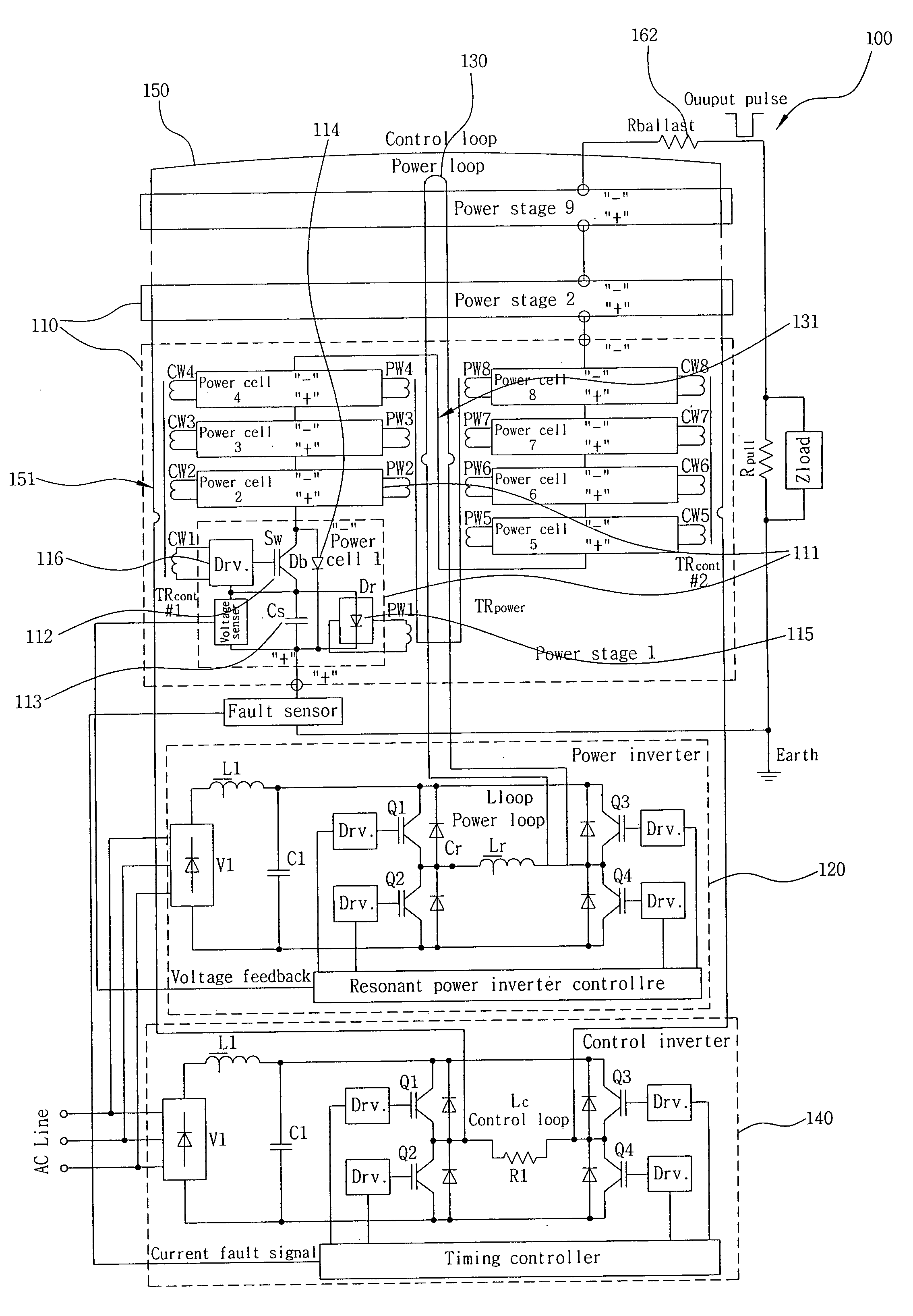
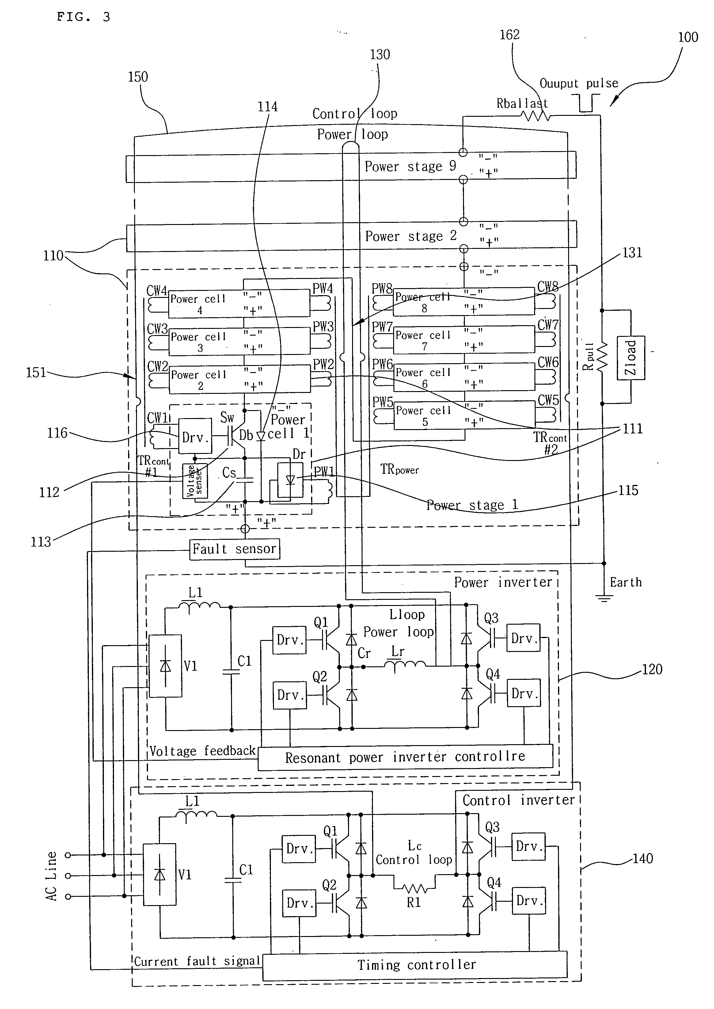
[0045]A pulse power generator according to the present invention has been configured from the point of view that all the semiconductor switches are connected in series with one another such that if voltage applied to each semiconductor switch is lowered to a voltage level which one semiconductor switch can withstand, a serious problem can be overcome in that the semiconductor switches are damaged sequentially like a chain reaction in case where the gate signals are not synchronized.

[0046]FIG. 3 is a circuit diagram illustrating the construction of a pulse power generator using a semiconductor according to the present invention.

[0047]As shown in FIG. ...


PUM


Abstract

The present invention provides a pulse power generator using a semiconductor switch, which enables its lifespan to be significantly improved, allows for its miniaturization, and makes it possible to diversely control a high-voltage pulse output finally. According to the pulse power generator, it is possible to address and solve a difficulty in driving the semiconductor switch in series, i.e., the problems related to synchronization and insulation of a driving power supply, and to include a circuit which can cope with the generation of arc and short circuit to thereby significantly improve device protecting performance and stability of the pulse power generator.

Description

CROSS-REFERENCE TO RELATED APPLICATIONS[0001]This application claims the benefit under 35 U.S.C. §119(a) of Korean Patent Application No. 10-2006-0107571, filed in the Korean Intellectual Property Office on Nov. 2, 2006, the entire contents of which are incorporated herein by reference.BACKGROUND OF THE INVENTION[0002](a) Field of the Invention[0003]The present invention relates to a pulse power generator using a semiconductor switch, and more particularly to such a pulse power generator using a semiconductor switch, which enables its lifespan to be significantly improved, allows for its miniaturization, and makes it possible to diversely control a high-voltage pulse output finally.[0004](b) Background Art[0005]In general, a high-voltage pulse generating circuit uses various test equipment and a plasma generator (PSII, etc.) as a load. A conventional high-voltage pulse generating circuit embraces lots of problems in terms of lifespan of the switch, variation in the pulse width, incr...

Claims


Application Information

Patent Timeline
Patent Type & Authority Applications(United States)
IPC IPC(8): H03K3/64H02M3/18
CPCH03K3/57H02M3/18
Inventor RYOO, HONG JEKIM, JONG SOORIM, GEUN HIEGUSSEV, GUENNADI
Owner KOREA ELECTROTECH RES INST
Why Eureka
Try Eureka