
Edge design for ePTFE-reinforced membranes for PEM fuel cells

a fuel cell and eptferein-reinforced technology, applied in the field of fuel cells, can solve the problems of relatively high manufacturing cost of membrane electrode assemblies, difficult proton barrier structures, and high cost of construction

Active Publication Date: 2008-05-08
GM GLOBAL TECH OPERATIONS LLC
View PDF6 Cites 5 Cited by
  • Summary
  • Abstract
  • Description
  • Claims
  • Application Information

AI Technical Summary

Benefits of technology

[0019]The present invention provides many benefits over the prior art, including but not limited to: (1) reduced mechanical singularities at interface; (2) lower costs (material and manufacturing); (3) easier manufacturing; (4) reduced thickness variation at the edge; and (5) reduced risk of delamination.

Problems solved by technology

The catalytic particles are typically costly precious metal particles.
These membrane electrode assemblies are relatively expensive to manufacture and require certain conditions, including proper water management and humidification, and control of catalyst fouling constituents such as carbon monoxide (CO), for effective operation.
Unfortunately, these types of proton barrier structures are rather difficult and expensive to construct, and have not produced entirely satisfactory results.

Method used


Image

  • Edge design for ePTFE-reinforced membranes for PEM fuel cells
  • Edge design for ePTFE-reinforced membranes for PEM fuel cells
  • Edge design for ePTFE-reinforced membranes for PEM fuel cells

Examples


Embodiment Construction

[0014]The following description of the embodiment of the invention is merely exemplary in nature and is in no way intended to limit the invention, its application, or uses.

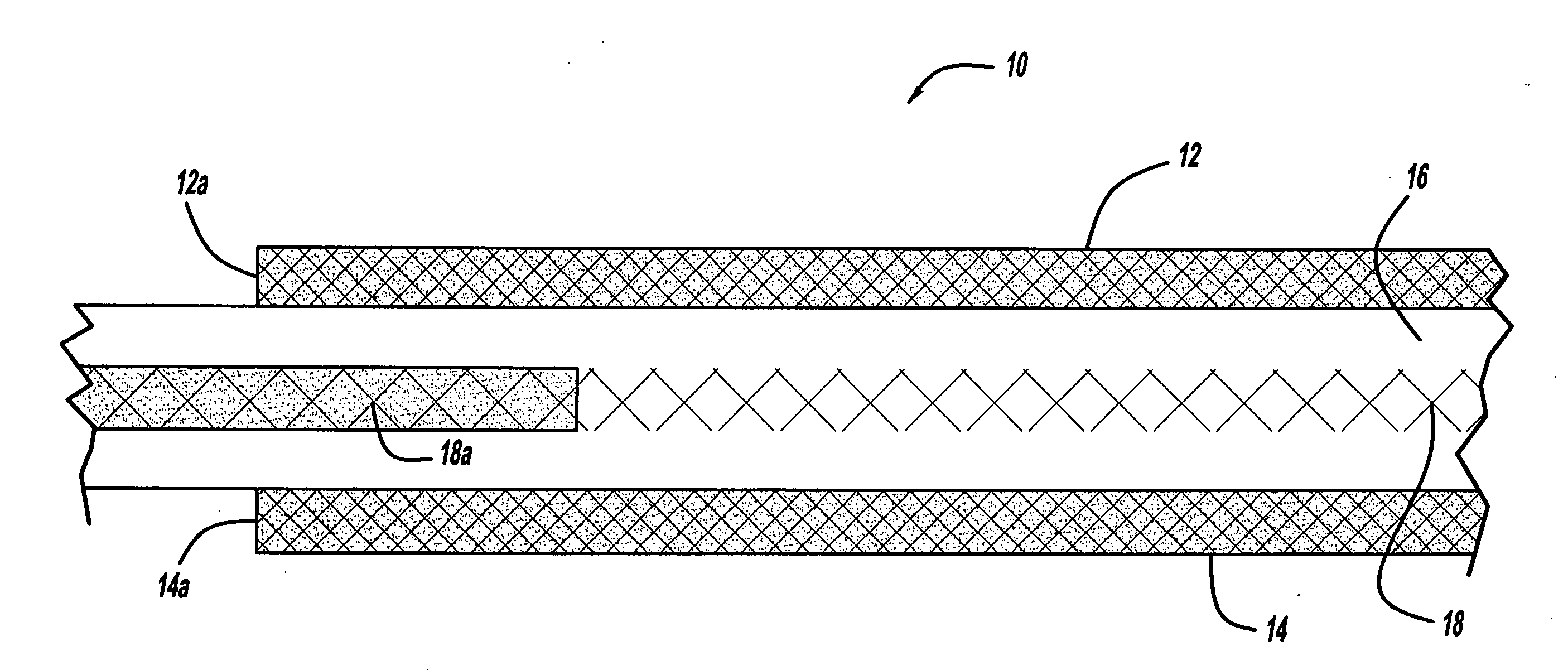
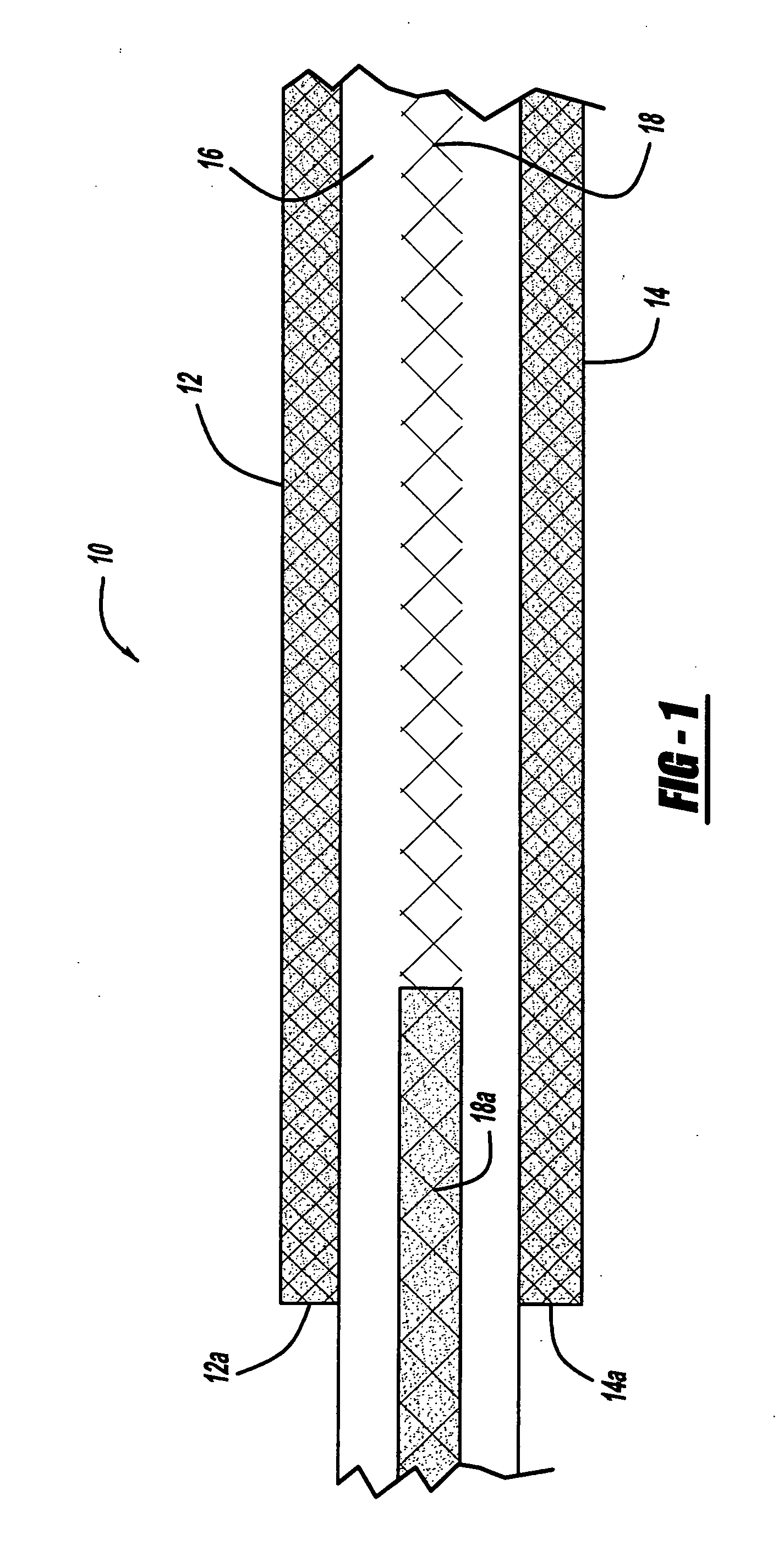
[0015]Referring to FIG. 1, there is shown a schematic view of a membrane electrode assembly 10, in accordance with the general teachings of the present invention. The membrane electrode assembly 10 includes two spaced and opposed electrode layers 12 and 14, respectively, such as cathode and / or anode layers. The electrode layers 12 and 14, respectively, are provided with edge portions 12a and 14a, respectively.

[0016]Disposed between the electrode layers 12 and 14 is a membrane layer 16, such as, but not limited to, an ionomer membrane layer. A reinforcing layer 18, such as, but not limited to, ePFTE is disposed within and imbibed by the ionomer material of the membrane layer 16. The reinforcing layer 18 includes an imbibed portion 18a, wherein the reinforcing layer 18 is imbibed with a proton-impermeable polymer in...


PUM

PropertyMeasurementUnit
thicknessesaaaaaaaaaa
proton impermeableaaaaaaaaaa
thicknessaaaaaaaaaa

Abstract

Edge designs, especially for ePTFE-reinforced membranes for proton exchange membrane (PEM) fuel cells, wherein the designs provide a proton barrier at the electrode edge of the PEM fuel cell membrane electrode assembly (MEA) to provide, among other things, resistance to membrane chemical degradation. A portion of the ePTFE layer is imbibed with a proton-impermeable polymer at the electrode edge. The polymer can include, without limitation, B-staged epoxides, B-staged phenolics, hot melt thermoplastics, and / or thermosets or thermoplastics cast from liquid dispersions.

Description

FIELD OF THE INVENTION[0001]The present invention relates generally to fuel cells and more particularly to improved edge designs of ePTFE-reinforced membranes for PEM fuel cells.BACKGROUND OF THE INVENTION[0002]Fuel cells have been used as a power source in many applications. For example, fuel cells have been proposed for use in electrical vehicular power plants to replace internal combustion engines. In proton exchange membrane (PEM)-type fuel cells, hydrogen is supplied to the anode of the fuel cell and oxygen is supplied as the oxidant to the cathode. PEM fuel cells include a membrane electrode assembly (MEA) comprising a thin, proton transmissive, non-electrically conductive solid polymer electrolyte membrane having the anode catalyst on one of its faces and the cathode catalyst on the opposite face. The MEA is sandwiched between a pair of electrically conductive elements, sometimes referred to as the gas diffusion media components, that: (1) serve as current collectors for the ...

Claims


Application Information

Patent Timeline
Patent Type & Authority Applications(United States)
IPC IPC(8): H01M8/02H01M4/00
CPCH01M8/0291H01M8/1044Y02E60/521H01M8/106H01M2300/0082H01M8/1053H01M8/0289Y02E60/50
Inventor PETTIT, WILLIAM H.BUDINSKI, MICHAEL K.GU, WENBIN
Owner GM GLOBAL TECH OPERATIONS LLC
Learn More