Systems and Methods of Cooling Blast Furnaces

a technology of systems and methods, applied in indirect heat exchangers, furnaces, lighting and heating apparatus, etc., can solve the problems of affecting the installation process, affecting the cooling effect, and the refractory lining may be subject to extreme mechanical wear, so as to improve the installation effect, simplify the design, and increase the cost

Inactive Publication Date: 2008-05-15
ANDCO METAL IND PROD
View PDF5 Cites 37 Cited by
  • Summary
  • Abstract
  • Description
  • Claims
  • Application Information

AI Technical Summary

Benefits of technology

[0011]The plate cooler of Sharp also separates the coolant in the pipes within the cooling plate from an external coolant. In Sharp, the coolant is sealed within the pipes primarily to allow the pipes to move relative to the cooling plate in order to adjust cooling amounts within the plate. Furthermore, the external coolant in Sharp enters at least a chamber of the plate that is within the furnace shell. Thus, if that chamber is ruptured, an excessive amount of coolant may still enter the furnace. The pipes in Sharp are complex and contain a wick that significantly complicates the design and increases costs.
[0012]In light of at least the foregoing, it is beneficial to provide a cooling device for a ...

Problems solved by technology

Within a blast furnace, the refractory lining, burden materials, and the cooling plates and/or staves may be subject to extreme mechanical wear, high temperatures, gas channeling, and other occurrences that may erode and/or damage the refractory lining and cooling plates and/or staves.
Frequently, such damage to the cooling plates and/or staves can result in rupture of the plates and/or staves.
Uncontrolled coolant entering the blast furnace may cause operating problems and may damage the lining of the blast furnace.
The damage may be a loss of refractory lining exposing the steel shell to excessive temperatures.
Because the shell is typically both a pressure containing vessel and a structural support, it may be highly stressed.
Thus, over heating the shell may result in buckling and/or rupture of the shell.
The coolant may damage the lining locally or at any portion of the furnace below the leak.
Uncontrolled coolant entering the blast furnace m...

Method used


Image

  • Systems and Methods of Cooling Blast Furnaces
  • Systems and Methods of Cooling Blast Furnaces
  • Systems and Methods of Cooling Blast Furnaces

Examples


Embodiment Construction

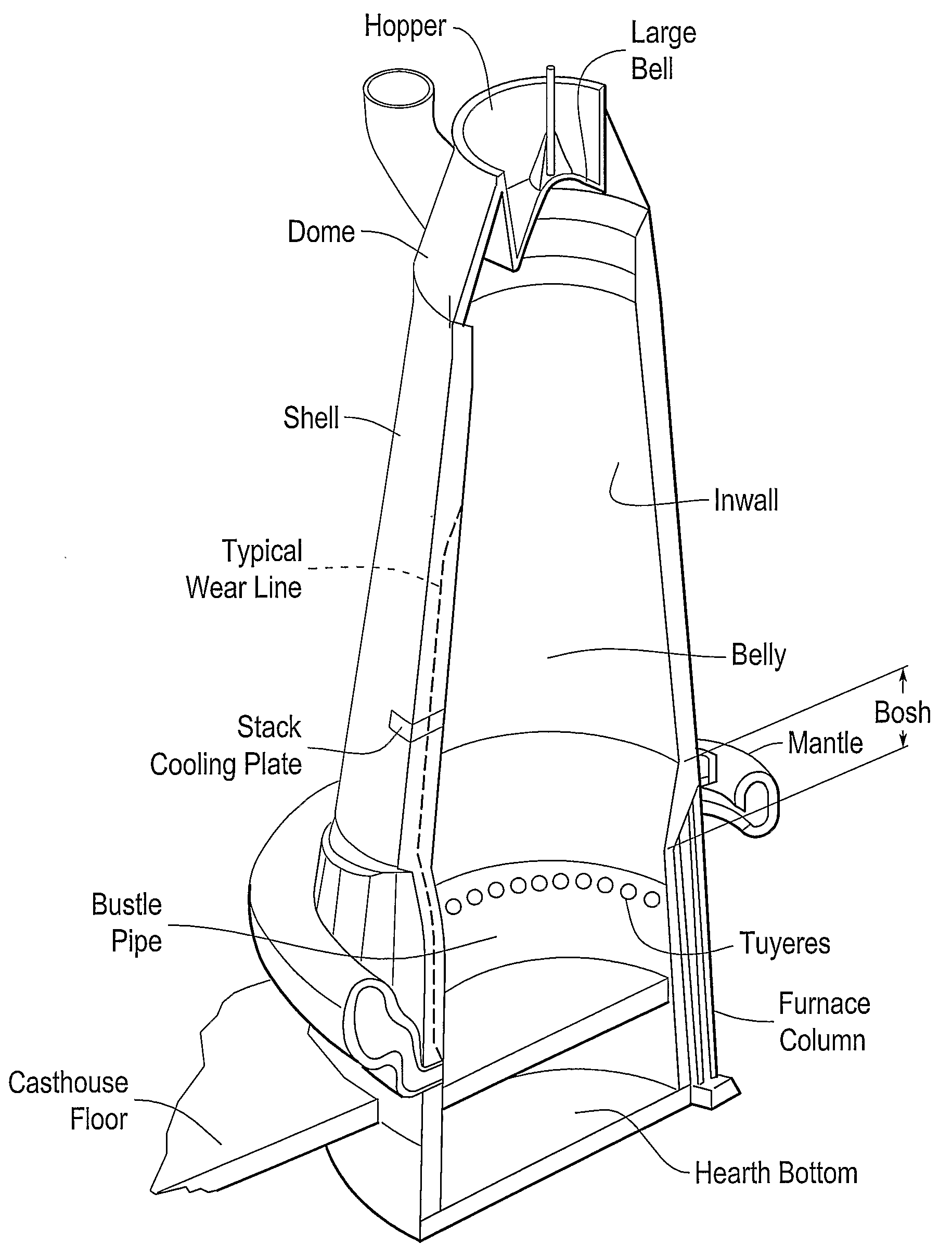
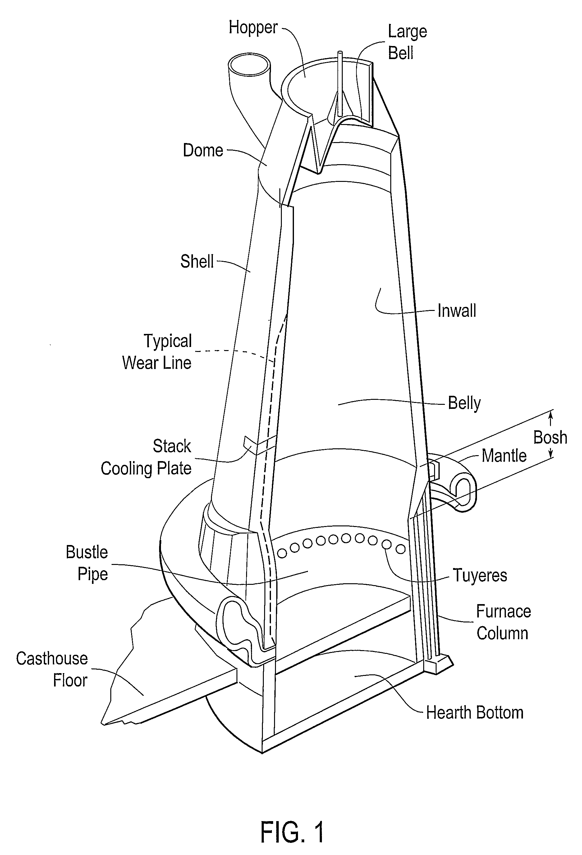
[0023]Blast furnaces may be used to convert iron bearing raw materials into a form that can be easily transformed into steel. A blast furnace is typically a large refractory lined steel vessel in which pellets and / or sinter, coke, and flux materials may be charged into the furnace top. High temperature air at high pressure may be blown into the bottom of the furnace. Molten iron and slag accumulate at the bottom of the furnace and may be removed periodically. FIG. 1 shows an exemplary blast furnace.

[0024]As shown in FIG. 1, the lower portion of the furnace is called the hearth. The steel jacket surrounding the hearth is vertical or slightly conical. The jacket may be lined with refractory material (e.g., carbon, graphite, silicon carbide, and / or ceramics) and may be cooled with staves or external shell sprays. The hearth bottom may be lined with refractory material. One or more iron notches may be located on or above the hearth floor. The iron notches permit iron and or slag to be r...


PUM


Abstract

Systems and methods provide a cooling device for a blast furnace that may prevent an excessive amount of coolant from entering the blat furnace and may be easily installed in a conventional blast furnace. Systems and methods may provide a cooling device for a blast furnace that may prevent an excessive amount of coolant from entering the blast furnace and may be simple and cost effective to manufacture. The end of a heat pipe (202) that is outside of the furnace may be configured to interact with a heat sink (210). The heat sink (210) may be for example, a separate amount of coolant that is circulated outside of the furnace, an evaporative cooling system, and/or any other system or method of cooling the heat pipe (202) that transfers heat from the heat pipe (202) to the heat sink (210). Because the coolant within the heat pipe (202) is sealed within the heat pipe (202), only the small, fixed amount of coolant that. is within the heat pipe (202) will enter the furnace should the cooling plate (200) rupture. Thus, substantial damage to the furnace, extensive repairs, and/or long periods of non-production may be avoided.

Description

BACKGROUND[0001]1. Related Technical Fields[0002]Related fields include systems and methods for cooling blast furnaces. Related fields include cooling plates, cooling staves, cigar coolers, and tuyeres.[0003]2. Related Art[0004]Conventional blast furnaces cool the blast furnace with shell sprays, cooling plates, or more recently, cooling staves. Conventional cooling plates may be arranged in the tuyere breast, bosh, and / or stack of a blast furnace. The cooling plates may be inserted through an opening in the shell of the furnace and may be interposed between a refractory lining. The cooling plates have cavities that provide passages. Coolant, such as, for example, water at an elevated pressure is pumped through the passages in order to cool the cooling plates. The cooled plates thus cool the refractory lining.[0005]Conventional cooling staves are arranged within a blast furnace and are arranged substantially parallel to a steel shell of the blast furnace. The cooling staves typicall...

Claims


Application Information

Patent Timeline
IPC IPC(8): C21B7/10
CPCC21B7/10F27B1/24F27D1/12F27D9/00F28D15/0233F27D2009/0048F27D2009/0062F28D15/02F27D2009/0018
Inventor PYNE, WILLIAM E.
Owner ANDCO METAL IND PROD
Why Eureka
Try Eureka