Cylindrical bandstop filters for medical lead systems

a technology of cylindrical bandstop and lead system, which is applied in the direction of feed-through capacitor, structural fixed capacitor combination, therapy, etc., can solve the problems of significant challenge in the implementation of this technology in implantable leads, significant heating at points of high current concentration

Inactive Publication Date: 2008-05-22
WILSON GREATBATCH LTD
View PDF79 Cites 170 Cited by
  • Summary
  • Abstract
  • Description
  • Claims
  • Application Information

AI Technical Summary

Benefits of technology

[0012]Preferably, the electrical components of the bandstop filter are hermetically insulated from contact with biological fluids or cells. The bandstop filter may be comprised of biocompatible materials. Alternatively, the bandstop filter may be hermetically sealed within a biocompatible material coating the bandstop filter. In yet another embodiment, the bandstop filter is disposed within a biocompatible cylinder having a first biocompatible end cap attached to a first end thereof, and a second biocompatible end cap attached to a second end thereof so as to prevent body fluids or cells from entering therein. The first end of the inductor winding is conductively coupled to the first end cap, and the second end of the inductor winding is conductively coupled to the second end cap. The first and second end caps are adapted to be conductively coupled to the lead wire or an electrode of the medical lead system.

Problems solved by technology

This is due largely to the patient safety issue that results when the strong electromagnetic fields of an MRI system interact with the antenna-like therapy delivery leads of an active implantable medical device.
These current loops can cause significant heating at points of high current concentration, the most significant of which is the distal tip, where the lead system makes direct contact with myocardial tissue.
Implementation of this technology in implantable leads is a significant challenge.

Method used


Image

  • Cylindrical bandstop filters for medical lead systems
  • Cylindrical bandstop filters for medical lead systems
  • Cylindrical bandstop filters for medical lead systems

Examples


Embodiment Construction

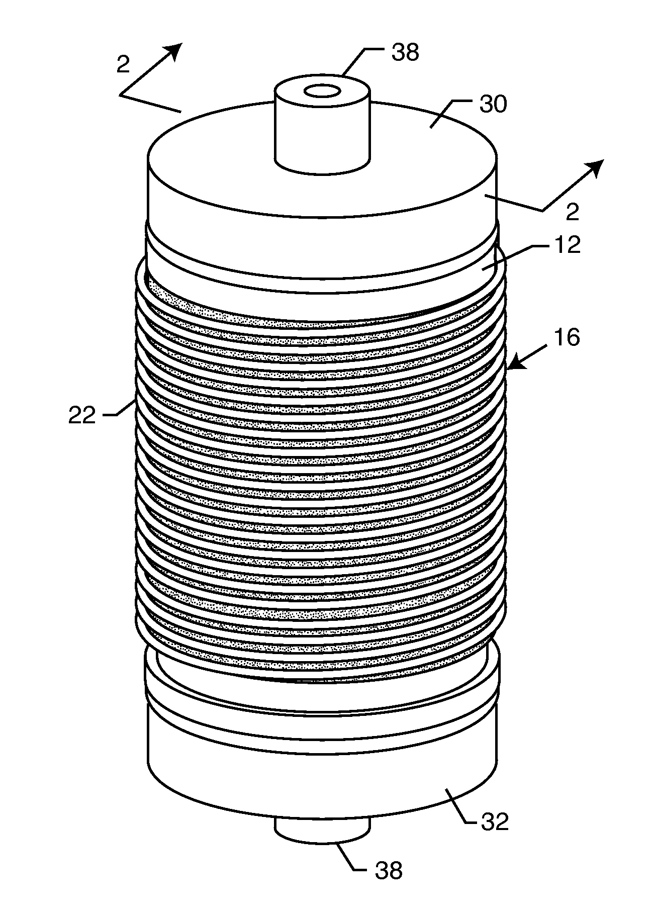
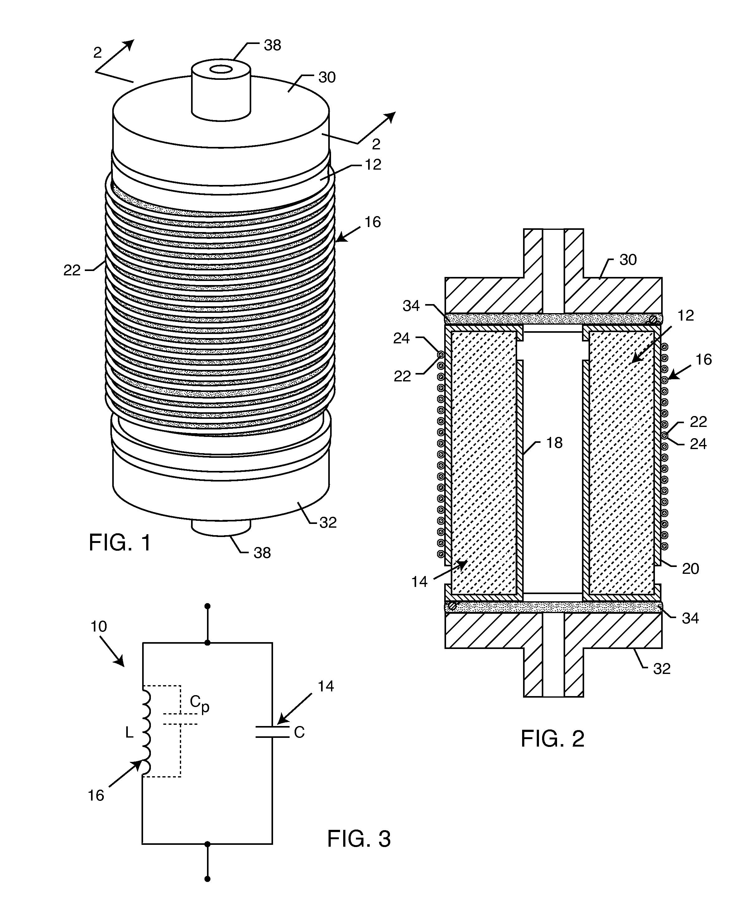
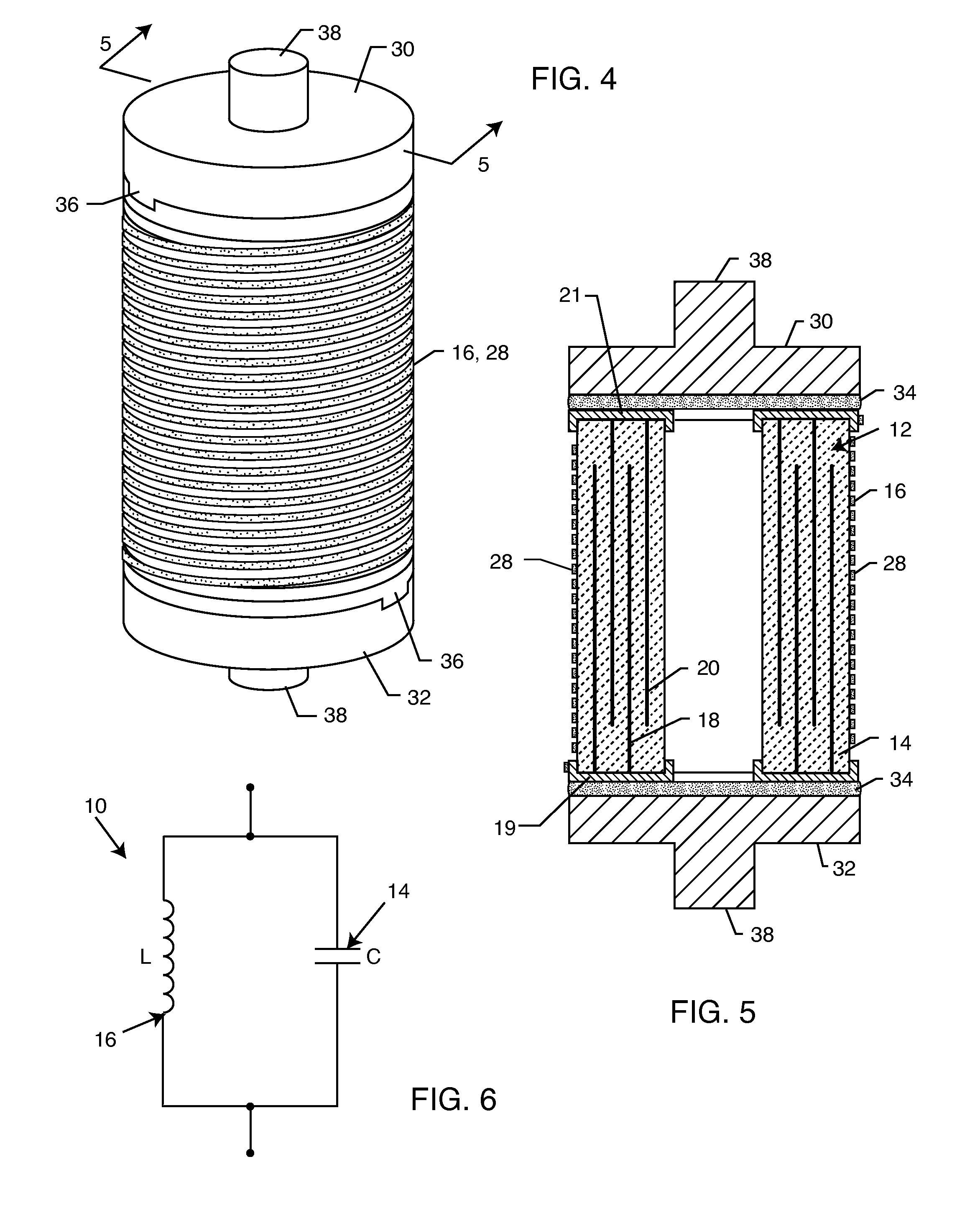
[0038]The present invention describes a novel way to build a parallel inductor and capacitor circuit 10 in such a way that it is comprised of a single, cylindrical substrate 12, typically comprised of dielectric material. In this manner, the component can retain the cylindrical shape of the lead system, and be directly portable to existing lead technologies.

[0039]The cylindrical substrate 12 can be hollow, comprising an outer diameter and an inner diameter, as needed. The aspect ratio between outer diameter and inner diameter is dependent on lead design, specific strength requirements, and required electrical performance. The single substrate is effectively split into two portions, one comprising the capacitive element 14, and the other comprising the inductive element 16. The capacitive element 14 and inductive element 16 are in parallel with one another, electrically, and are selected so as to resonate at one or more frequencies, typically MRI pulsed frequencies.

[0040]With referen...


PUM


Abstract

A one-piece cylindrical bandstop filter for medical lead systems incorporates parallel capacitive and inductive elements in a compact cylindrical configuration. The compact cylindrical configuration of the bandstop filter does not add significantly to the size or weight of the medical lead system. Preferably, the bandstop filters are of biocompatible materials or hermetically sealed in biocompatible containers. The parallel capacitive and inductive elements are placed in series with the medical lead system, and are selected so as to resonate at one or more selected frequencies, typically MRI pulsed frequencies.

Description

BACKGROUND OF THE INVENTION[0001]Magnetic resonance imaging (MRI) is currently contra-indicated for patients who have implanted medical devices. This is due largely to the patient safety issue that results when the strong electromagnetic fields of an MRI system interact with the antenna-like therapy delivery leads of an active implantable medical device. It is well documented that the RF signals that are generated by the MRI system can attenuate along the length of a lead body and create induced current loops. These current loops can cause significant heating at points of high current concentration, the most significant of which is the distal tip, where the lead system makes direct contact with myocardial tissue.[0002]As disclosed in U.S. patent application Ser. No. 11 / 558,349 filed Nov. 9, 2006, the contents of which are incorporated herein by reference, a novel method to minimize the expected heating at the distal tip is to incorporate a bandstop filter. This bandstop filter is co...

Claims


Application Information

Patent Timeline
Patent Type & Authority Applications(United States)
IPC IPC(8): H03H7/12
CPCA61N1/056A61N1/3718A61N2001/086H03H2001/005H01G4/40H03H7/0161H03H2001/0035H01G4/35A61N1/086
Inventor DABNEY, WARREN S.BILLINGS, KENNETH D.HAUSER, BETHANY M.HILL, BRENDENKUSTRA, GABESTEVENSON, ROBERT A.
Owner WILSON GREATBATCH LTD
Why Eureka
Try Eureka