Method And System For Dynamic Low Dose X-ray Imaging

a low-dose x-ray and dynamic technology, applied in the field of x-ray imaging, can solve the problems of large impediments of prior art interventional imaging, large number of x-rays, and inability to solve the problem of high subject and attendant dosage, and achieve the effect of reducing the scattering of detected photons

Inactive Publication Date: 2008-05-22
FOREVISION IMAGING TECH LLC
View PDF13 Cites 125 Cited by
  • Summary
  • Abstract
  • Description
  • Claims
  • Application Information

AI Technical Summary

Benefits of technology

[0015] Slot-scanning for chest imaging has been demonstrated to reduce detected scattered photons by a factor of two to three. In turn this enables Bucky grid elimination and an associated radiation dose savings likely approaching a factor of two. An additional dose savings is obtained by projecting and rotating a slot beam in accordance with the geometry described herein below. Attendant dose savings is proportional to the patient's.

Problems solved by technology

Although X-ray imaging systems for this purpose are widely available, prior-art systems and approaches are significantly limited.
In particular, prior art interventional imaging poses the major impediments of high subject radiation dose and cumulative physician exposure to radiation.
However, these improvements have not resolved the issues of high subject and attendant dosage.
Current technologies are further limited, in part, due to use of large area detectors and large exposure area beams.
Large exposed areas translate into high detector costs and the need to reject scattered X-rays at the detector.
Use of a Bucky grid therefore adds to the aforementioned high subject and attendant dose; furthermore, large exposed areas result in relatively low refresh rates over the entire image.
For example, read-out of an entire large area detector, or a large area of such a detector, limits the imaging refresh rate.
Cardiology and neurology interventions, which typically require the insertion of a catheter or similar interventional device in the subject's vasculature, can necessitate continuous or intermittent subject exposures for extended durations, resulting in high X-ray doses.
Interventional radiologists, cardiologists and other attending staff are also subject to significant X-ray exposure and dose, to such a degree that dose limitation regulations may prevent them from active work for a significant fraction of their available time, thus leading to underutilization of expensive resources.
Three-dimensional (3D) imaging currently requires complex and expensive systems.
In addition, most currently available 3D imaging systems also deliver high subject doses, and often limit access to the subject due to use of a gantry, a large area detector or a combination of area detectors.
The major limitations of fluoroscopy as an image-guided interventional tool are X-ray dose, three-dimensional (3D) structure superposition in a projection image, and lack of structure contrast.
X-ray imaging systems are often designed to be X-ray noise limited.
Currently, no specific dose guidelines beyond “as low-as reasonably achievable” are provided to the user.
In practice, most existing detectors exhibit lower detective quantum efficiency (DQE) at lower exposures, thereby setting another lower limit to the X-ray dose.
As interventional tools become smaller and more easily navigable, increasingly complex interventions are planned on smaller structures.
Object and structure visualization are often limited by both lack of inherent X-ray contrast and 3D structures superposition.
Typically, contrast enhancing dyes are used to increase contrast but in some cases these have been shown to pose toxic risk especially to the kidneys.

Method used


Image

  • Method And System For Dynamic Low Dose X-ray Imaging
  • Method And System For Dynamic Low Dose X-ray Imaging
  • Method And System For Dynamic Low Dose X-ray Imaging

Examples


Embodiment Construction

[0073] It should be noted that the matter contained in the following description and / or shown in the accompanying drawings may be embodied in various forms, and should therefore be interpreted as illustrative, and not in a limiting sense. Elements shown in the drawings are not necessarily to scale and may be exaggerated, enlarged or simplified, to facilitate understanding of the invention. The system implementation according to the various shown embodiments is amenable to automated controls.

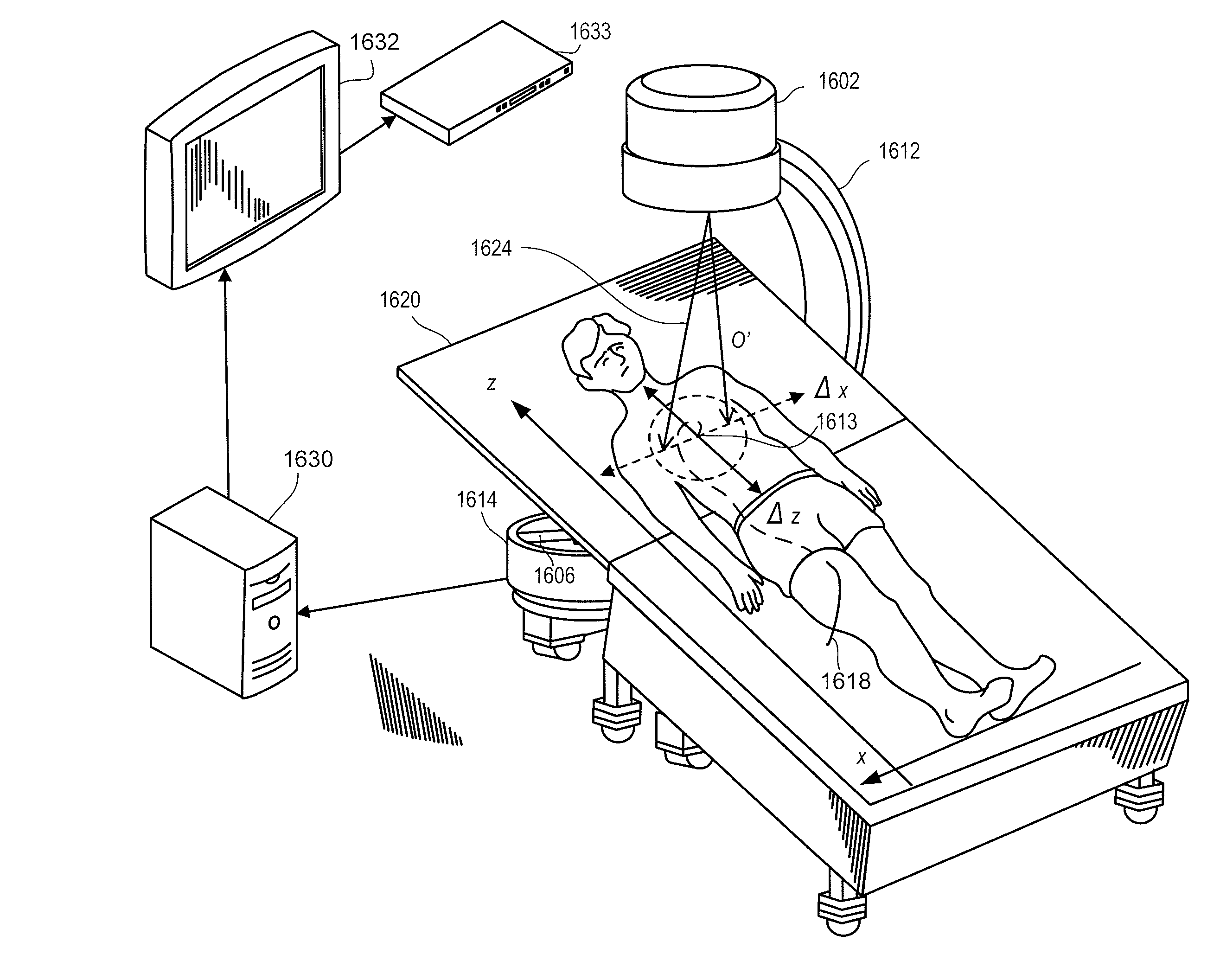
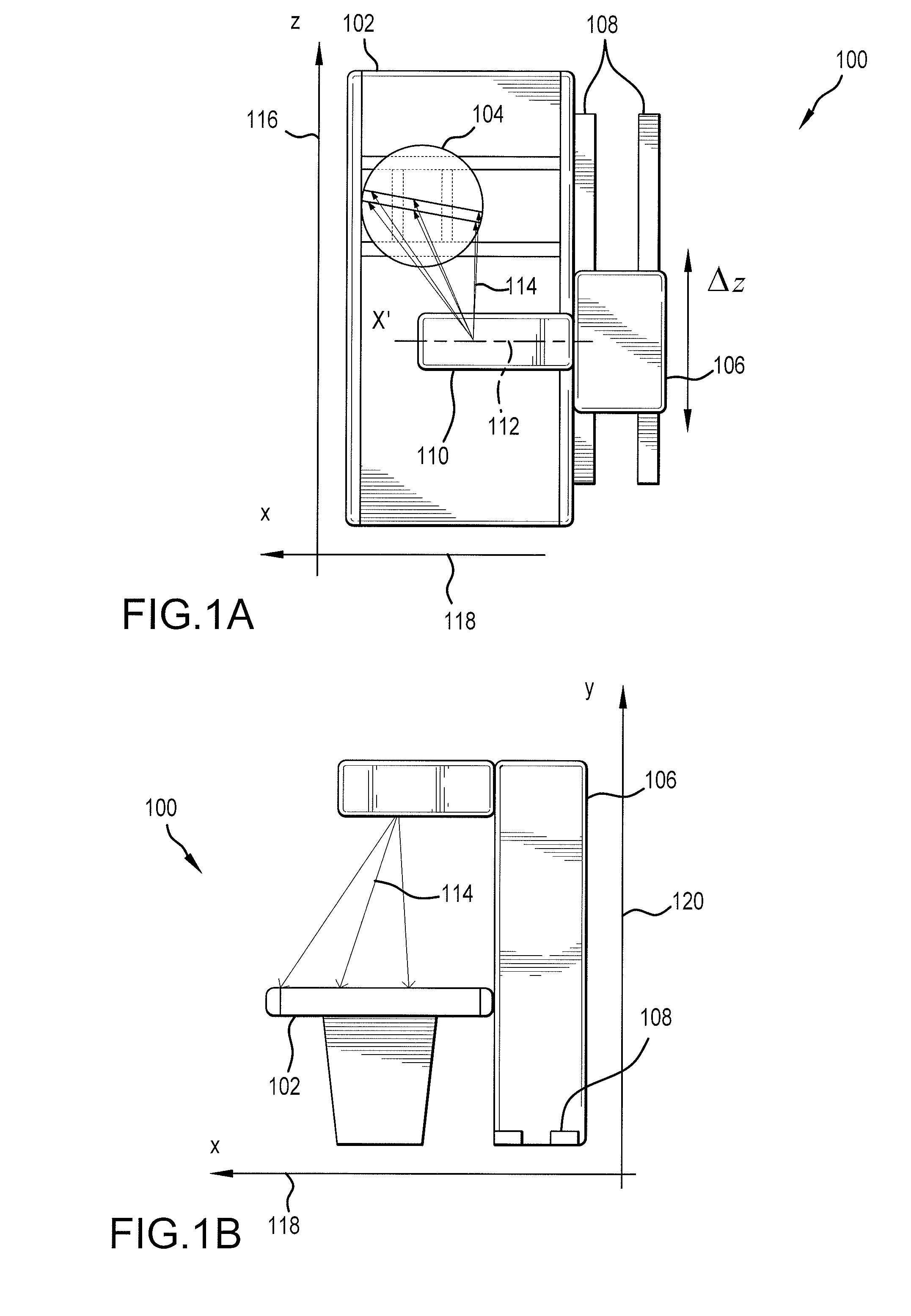
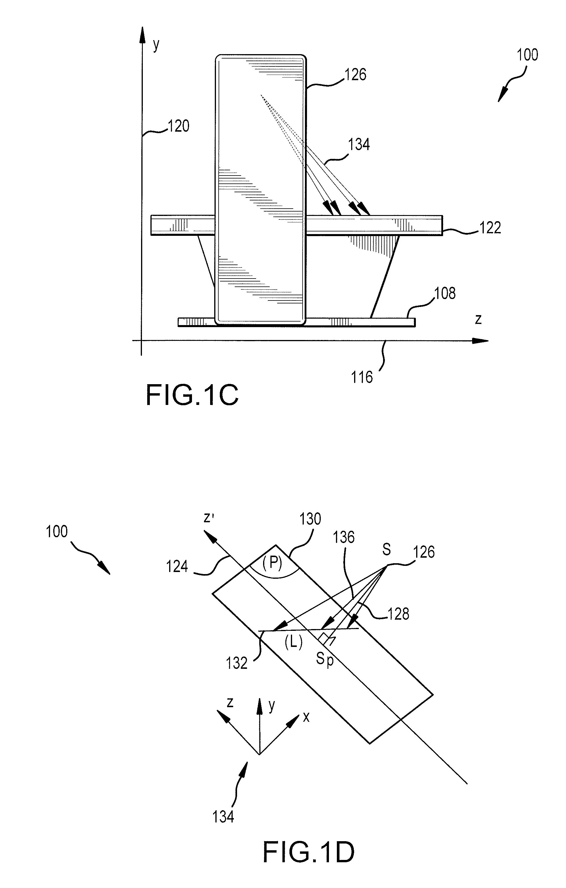
[0074] Turning now to FIG. 1A, a system 100 for dynamic low dose X-ray imaging is shown in a top orthogonal view. System 100 for example allows a significant reduction in subject and physician dose while permitting effective performance of an interventional or diagnostic procedure. A frame structure (or cradle) 102, designed for placement beneath or within a subject table (see, e.g., table 1110; FIG. 11), permits relative motion of a detector assembly 104 (shown bounded by a circle) with respect...


PUM


Abstract

A method and system for performing fluoroscopic imaging of a subject has high temporal and spatial resolution in a center portion of the captured dynamic images. The system provides for reduced X-ray dose to the patient associated with that part of the X-ray beam associated with a peripheral portion of the captured images although temporal, and in some embodiments spatial, resolution is reduced in the peripheral portion of the image. The system uses a rotating collimator to produce an X-ray beam having narrow wing portions associated with the peripheral portions of the image, and a broader central region associated with the high resolution center portion of the images.

Description

CROSS-REFERENCE TO RELATED APPLICATIONS [0001] This application claims the benefit of priority to U.S. Provisional Patent Application No. 60 / 881,356, filed Jan. 19, 2007, and U.S. Provisional Patent Application No. 60 / 931,614, filed May 24, 2007. This application is also a continuation-in-part of U.S. Ser. No. 11 / 351,909, filed Feb. 10, 2006, and a continuation-in-part of U.S. Ser. No. 11 / 351,446, filed Feb. 10, 2006, both of which claim the benefit of priority to U.S. Provisional Patent Application No. 60 / 652,127, filed Feb. 11, 2005, and U.S. Provisional Patent Application No. 60 / 654,922, filed Feb. 22, 2005. Each of the aforementioned patent applications is incorporated herein by reference in its entirety.BACKGROUND [0002] This disclosure relates to X-ray imaging, and more particularly to the dynamic low-dose imaging of an object or subject with a moving detector, as well as to the dynamic low-dose tomosynthesis and limited-angle tomographic imaging of a subject with a moving det...

Claims


Application Information

Patent Timeline
Patent Type & Authority Applications(United States)
IPC IPC(8): A61B6/03A61M25/098
CPCA61B6/025A61B6/4291A61B6/06A61B6/08A61B6/12A61B6/4028A61B6/4035A61B6/4216A61B6/4225A61B6/4233A61B6/4441A61B6/4447A61B6/4476A61B6/481A61B6/482A61B6/487A61B6/488A61B6/503A61B6/504A61B6/5282A61B6/541A61B6/542A61B6/587A61B6/032
Inventor BESSON, GUY M.
Owner FOREVISION IMAGING TECH LLC
Why Eureka
Try Eureka