Beam homogenizer, laser irradiation apparatus, and laser irradiation method

a laser irradiation and beam homogenizer technology, applied in the field of beam homogenizers, laser irradiation apparatuses, laser irradiation methods, can solve the problems of single mode laser beams, interference of laser beams, annealing, etc., to avoid or reduce the amount of heat energy needed, the effect of reducing the amount of heat energy required

Active Publication Date: 2008-05-22
SEMICON ENERGY LAB CO LTD
View PDF15 Cites 13 Cited by
  • Summary
  • Abstract
  • Description
  • Claims
  • Application Information

AI Technical Summary

Benefits of technology

[0029]In a case where a laser beam is emitted from a continuous wave laser apparatus or a pseudo continuous wave laser apparatus, a frequency of oscillation of a beam homogenizer, a slit, and a projection lens f, a scanning velocity of a laser beam on a surface to be irradiated V, and a length of the laser beam in a scanning direction on the surface to be irradiated d satisfy f≧V / d. Therefore, an effect that intensity distribution of the laser beam is temporally averaged becomes evident.
[0030]In the beam homogenizer of the present invention, the first reflecting mirror and the second reflecting mirror oscillate and thus intensity distribution of a laser beam at the exit of the beam homogenizer can be temporally averaged. Therefore, by using the beam homogenizer to be oscillated of the present invention, a portion in which intensity is not sufficiently high due to interference can be eliminated from the intensity distribution of a laser beam so that the distribution is homogenized, which makes it possible to heat the object to be irradiated homogeneously by the laser beam.
[0031]According to the present invention, by oscillating the slit, fluctuation in the intensity distribution of the laser beam due to diffraction can be avoided or reduced. Therefore, the amount of heat energy necessary for an object to be irradiated can be reliably supplied by the laser beam by using the oscillating slit of the present invention; accordingly, the object to be irradiated can be homogeneously heated by the laser beam.
[0032]According to the present invention, by oscillating the projection lens, fluctuation in the intensity distribution of the laser beam due to interference and diffraction of the laser beam can be avoided or reduced. Therefore, the amount of heat energy necessary for an object to be irradiated can be reliably supplied by the laser beam by using the oscillating projection lens of the present invention; accordingly, the object to be irradiated can be homogeneously heated by the laser beam.
[0033]Thus, as in the present invention, a laser beam passes through an oscillated beam homogenizer, an oscillated slit, or an oscillated projection lens, and then an object to be irradiated is irradiated with the laser beam, so that an advantageous effect of heating with the laser beam in the object to be irradiated can be obtained uniformly and reliably. For example, in the case of crystallizing an amorphous silicon film by laser beam irradiation, a crystalline silicon film having a homogeneous crystalline structure can be formed according to the present invention.

Problems solved by technology

However, extension of the light path and repeated reflections between the reflecting mirrors 11 and 12 result in interference of the laser beam.
A laser beam of the single mode, which is used for laser annealing, tends to interfere as compared to a laser of a multi mode.
In addition, the optical system using a slit, which is as described in Patent Document 2, has a problem of diffraction.
By diffraction, intensity of the vicinity of the ends of the laser beam might be not high enough or too high to completely melt the amorphous silicon film.
However, when a laser beam is used for irradiation light, interference and diffraction are inevitable physical phenomena.

Method used


Image

  • Beam homogenizer, laser irradiation apparatus, and laser irradiation method
  • Beam homogenizer, laser irradiation apparatus, and laser irradiation method
  • Beam homogenizer, laser irradiation apparatus, and laser irradiation method

Examples


embodiment mode 1

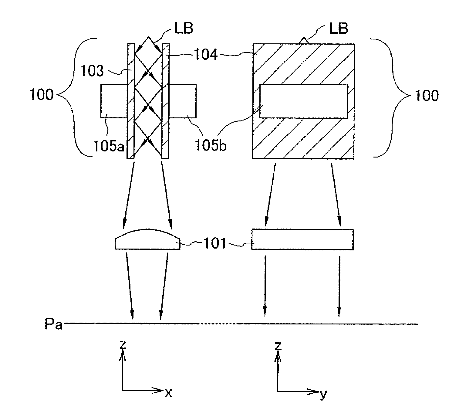
[0047]In this embodiment mode, an optical system having a beam homogenizer to be oscillated (or vibrated) is described. FIG. 1 is a plan view of the optical system of this embodiment mode. A plan view taken along x-z is shown on the left side and a plan view taken along z-y is shown on the right side. An x-direction, a y-direction, and a z direction are perpendicular to one another. FIG. 1 shows the optical system which has a surface to be irradiated, which is a plane parallel to an x-y plane, and performs scanning with a laser beam parallel in the y-direction.

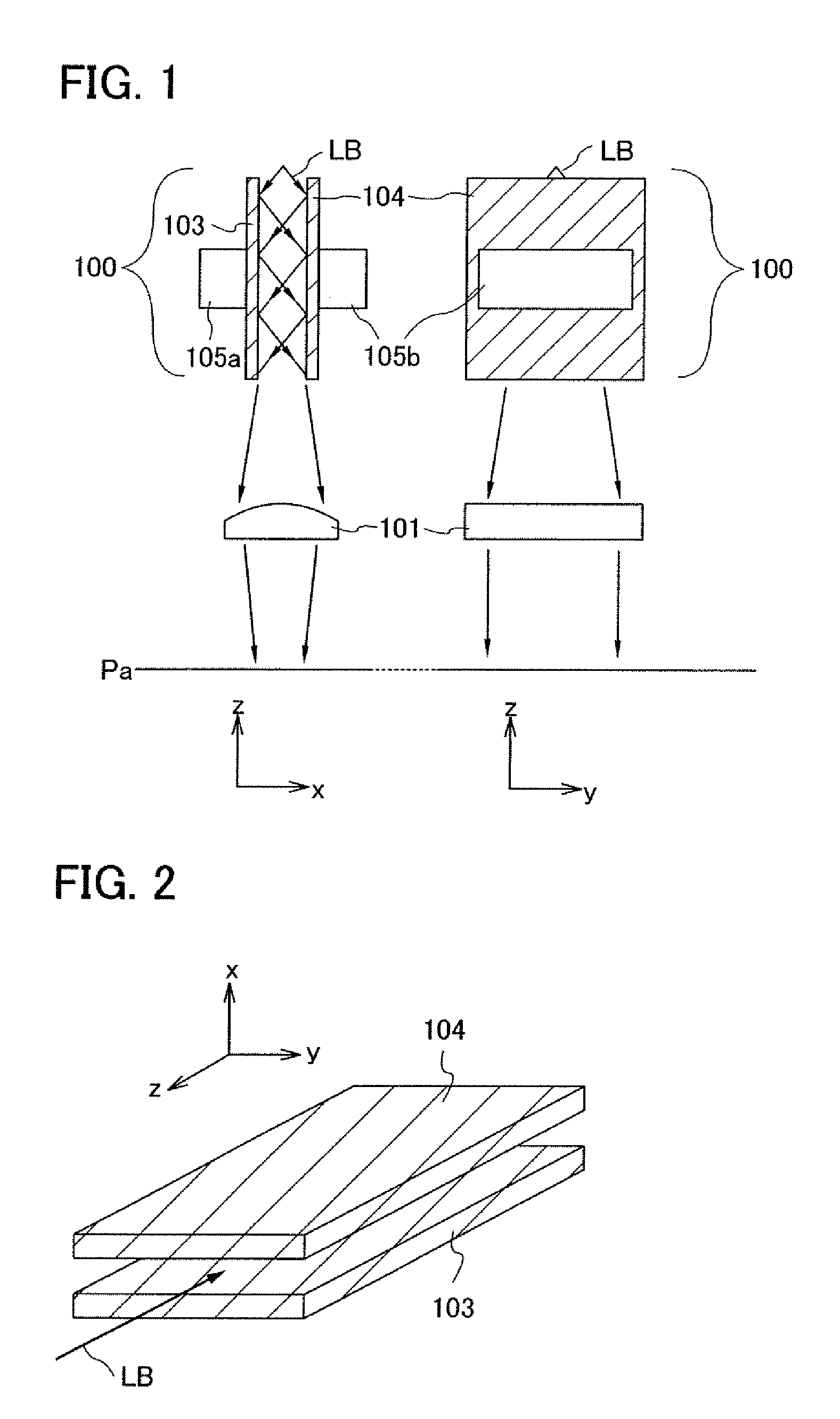
[0048]The optical system in FIG. 1 includes a beam homogenizer 100 and a projection lens 101. The beam homogenizer includes a first reflecting mirror 103 and a second reflecting mirror 104 which are rectangular. FIG. 2 is a three-dimensional perspective view of the beam homogenizer 100. An oscillator 105a is mounted on the first reflecting mirror 103, and an oscillator 105b is mounted on the second reflecting mirror 104. Oscil...

embodiment mode 2

[0065]In this embodiment mode, an optical system having a beam homogenizer to be oscillated is described. FIG. 4 is a plan view of the optical system of this embodiment mode. In FIG. 4, a plan view taken along x-z is shown on the left side and a plan view taken along z-y is shown on the right side similarly to in FIG. 1. The optical system in FIG. 4 is also an optical system which has a surface to be irradiated, which is a plane parallel to an x-y plane, and performs scanning with a laser beam parallel in the y-direction.

[0066]The optical system in FIG. 4 corresponds to the optical system in FIG. 1 to which a slit 120 is added. The slit 120 is provided between the exit side of the beam homogenizer 100 and the projection lens 101. The projection lens 101 projects an image of the slit 120 on the plane Pa. Similarly to in the optical system in FIG. 1, in the optical system in FIG. 4, an object to be irradiated is irradiated with the laser beam LB while the beam homogenizer 100 is oscil...

embodiment mode 3

[0070]In this embodiment mode, an optical system having a slit to be oscillated is described. FIG. 5 is a plan view of the optical system of this embodiment mode. In FIG. 5, a plan view taken along x-z is shown on the left side and a plan view taken along z-y is shown on the right side similarly to in FIG. 1. The optical system in FIG. 5 is also an optical system which has a surface to be irradiated, which is a plane parallel to an x-y plane, and scans a laser beam parallel in a y-direction.

[0071]As shown in FIG. 5, the optical system includes a slit 130 to be oscillated and the projection lens 101 provided on an exit side of the slit 130. The projection lens 101 is a lens for projecting an image of the slit 130 on the plane Pa. By the projection lens 101, the slit 130 and the plane Pa which is to be irradiated are in a conjugate relation.

[0072]The laser beam LB used for laser annealing is generally a laser beam of a single mode, and intensity distribution of the laser beam LB is Ga...


PUM

PropertyMeasurementUnit
wavelengthaaaaaaaaaa
distanceaaaaaaaaaa
frequency f1aaaaaaaaaa

Abstract

An effect of interference is eliminated and intensity of a laser beam is homogenized. The beam homogenizer 100 includes reflecting mirrors 103 and 104 which are provided so that reflecting surfaces thereof face each other. The laser beam LB propagates through a space between the reflecting mirrors 103 and 104 while being reflected therebetween, so that intensity distribution of the laser beam LB is homogenized, but the laser beam LB also interferes. The first reflecting mirror 103 and the second reflecting mirror 104 are oscillated in a direction perpendicular to a direction in which the laser beam LB is scanned, intensity distribution of the laser beam LB in an oscillation direction is temporally averaged.

Description

BACKGROUND OF THE INVENTION[0001]1. Field of the Invention[0002]The present invention relates to an apparatus and a method for irradiating a subject to be irradiated with a laser beam and also relates to the beam homogenizer used for a laser beam irradiation apparatus.[0003]2. Description of the Related Art[0004]In order to form an integrated circuit with a thin film transistor (hereinafter referred to as a TFT) having high mobility over a glass substrate, an amorphous silicon film is deposited over the glass substrate by a CVD method or the like and the amorphous silicon film is applied with heat energy to be crystallized, so that a crystalline silicon film is formed. For crystallizing the amorphous silicon film, laser annealing is used to avoid transformation of the glass substrate by heat.[0005]A crystalline structure of the crystalline silicon film crystallized by laser annealing depends on intensity of a laser beam. In a case where an amorphous silicon film is completely melted...

Claims


Application Information

Patent Timeline
Patent Type & Authority Applications(United States)
IPC IPC(8): G02B6/26G02B27/09H01L21/20H01L21/268
CPCG02B5/005G02B6/0096G02B19/0028G02B19/0052G02B27/0994
Inventor TANAKA, KOICHIRO
Owner SEMICON ENERGY LAB CO LTD
Why Eureka
Try Eureka