
Electric Oil Pump System and Controls for Hybrid Electric Vehicles

a hybrid electric vehicle and oil pump technology, applied in the field of electric oil pump system and controls for hybrid electric vehicles, can solve the problem of more electric motor torque, and achieve the effects of reducing engine cranking time, improving engine operating efficiency, and improving engine operation efficiency

Active Publication Date: 2008-05-29
FORD GLOBAL TECH LLC
View PDF24 Cites 38 Cited by
  • Summary
  • Abstract
  • Description
  • Claims
  • Application Information

AI Technical Summary

Benefits of technology

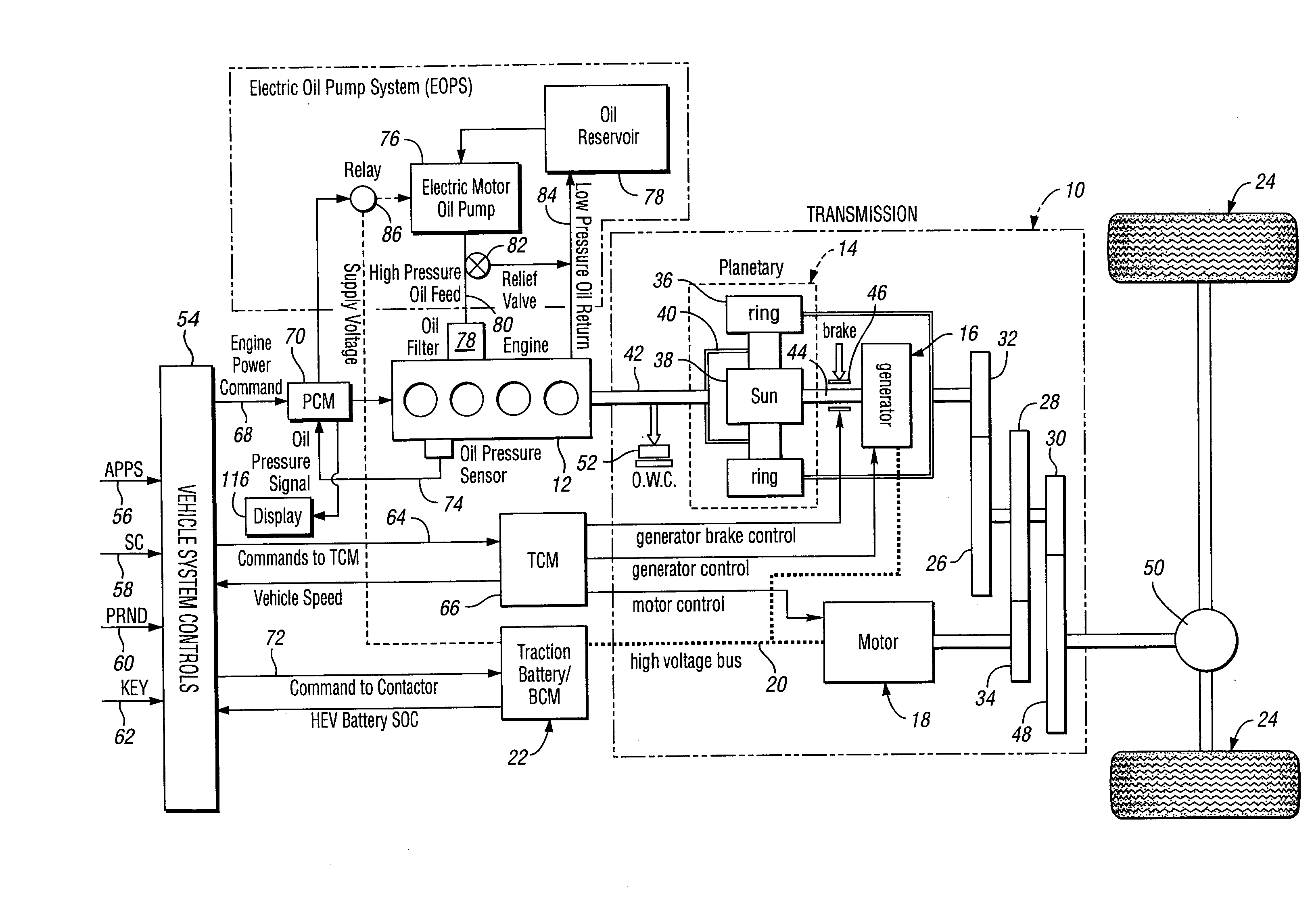
[0014]To avoid engine starts when the oil pump pressure is below an optimal value, the strategy of the invention will prime the engine with oil pressure before the initiation of the engine start event. This will avoid engine wear by providing critical oil films during the engine cranking mode.
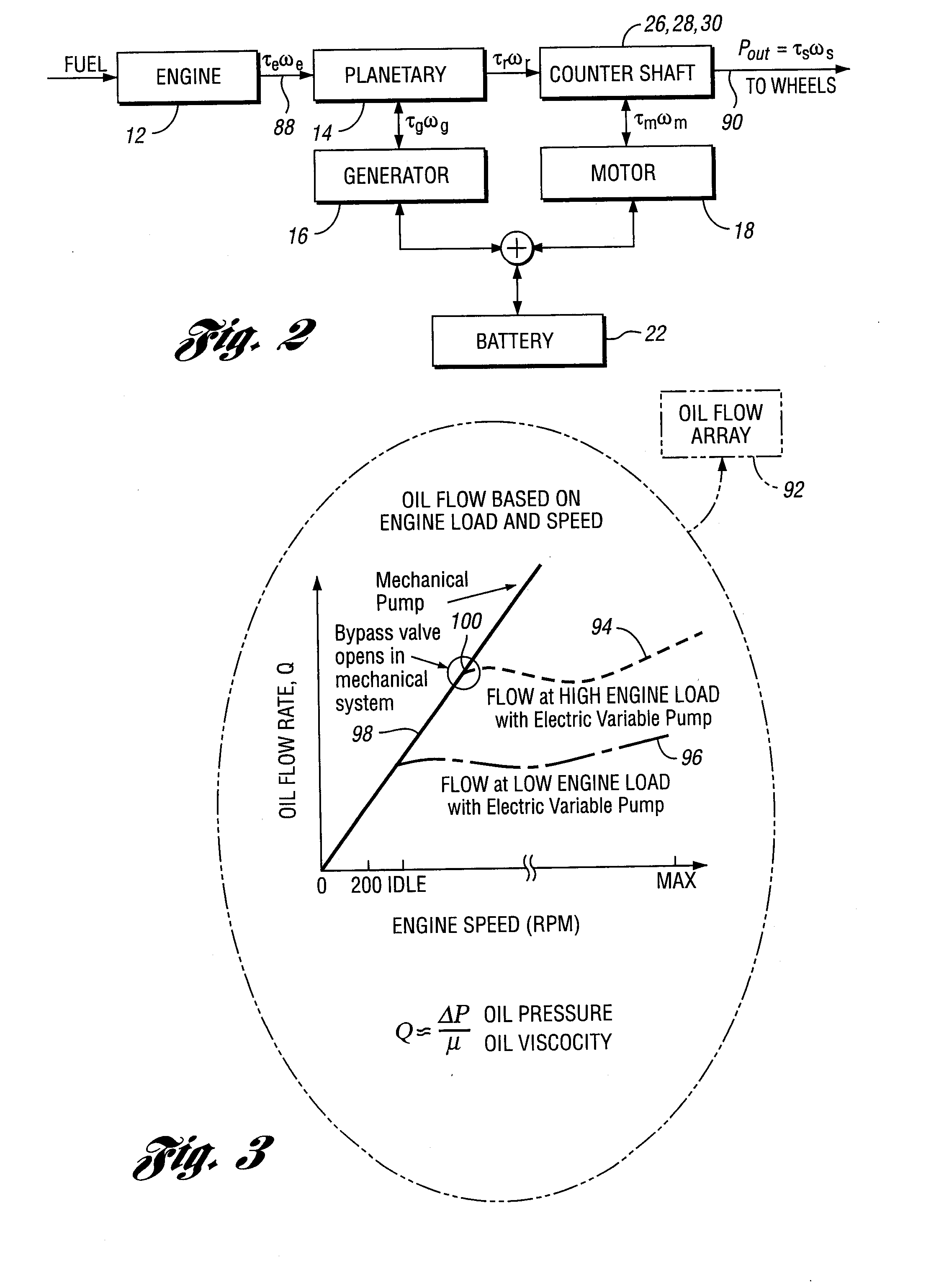
[0016]The engine oil lubrication system and strategy of the invention does not require the use of a bypass valve, as in the case of conventional engines, during normal high speed engine use. This improves the operating efficiency of the engine since the oil pump is not required to pump against a high output pressure. The strategy of the invention will make it possible to precisely meter oil flow through the engine so that an oil flow bypass circuit is not required for most operating conditions, even at high engine operating speeds.
[0017]If the engine includes a variable camshaft timing feature, the engine camshaft can be hydraulically pre-positioned using engine oil pressure before the engine is started. This will further improve engine operating efficiency and reduce the engine cranking time.
[0018]Since the oil pressure can be maintained while the engine is off, oil circulation can continue before the engine is cranked and fired. Thus it is possible to maintain the oil temperature at a higher value while the engine is shut down as the oil is circulated through the engine.

Problems solved by technology

If the engine oil filter becomes clogged, more electric motor torque is required to overcome flow resistance of the lubrication oil system.

Method used


Image

  • Electric Oil Pump System and Controls for Hybrid Electric Vehicles
  • Electric Oil Pump System and Controls for Hybrid Electric Vehicles
  • Electric Oil Pump System and Controls for Hybrid Electric Vehicles

Examples


Embodiment Construction

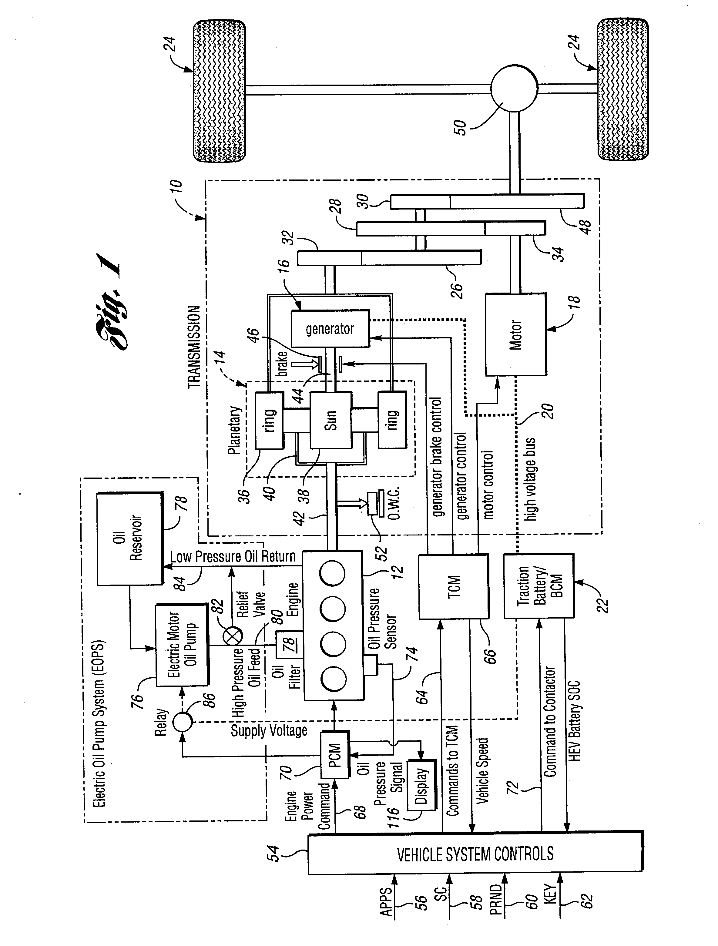
[0027]A hybrid electric vehicle powertrain with divided power flow paths is illustrated in FIG. 1, but the invention may be adapted for use also in other types of hybrid electric powertrains, including a pure series powertrain in which an engine drives a generator that is electrically coupled to an electric motor and a battery, the power output of the motor being transferred through a multiple ratio transmission to vehicle traction wheels. U.S. Pat. No. 7,117,964 discloses a powertrain with divided power flow paths as well as a pure series hybrid electric vehicle powertrain. The invention can be adapted also for a hybrid electric vehicle powertrain in which the engine and a motor-generator are separately connected to power transmission gearing so that electric power can complement engine power, and wherein an engine power disconnect clutch would be located between the engine and the motor-generator unit.

[0028]In FIG. 1, a divided power transmission is generally indicated at 10 and a...


PUM


Abstract

An engine lubrication oil flow control system and control method for an engine in a hybrid electric vehicle powertrain is disclosed. An engine lubrication oil pump is powered by a lubrication oil pump motor. Provision is made to start the lubrication pump motor at the initiation of engine cranking upon a transition from an engine-off driving mode to an engine-on driving mode. An engine oil pressure signal is used to indicate engine filter maintenance is needed. The oil pump motor may be powered by a vehicle powertrain traction battery.

Description

BACKGROUND OF THE INVENTION[0001]1. Field of the Invention[0002]The invention relates to a vehicle powertrain having an internal combustion engine with an engine oil lubrication pump powered by an electric motor.[0003]2. Background Art[0004]A hybrid electric vehicle powertrain typically has two electric machines and an internal combustion engine. In one operating mode, the engine and the electric machines define two power flow paths to vehicle traction wheels. One electric machine functions as a generator in one operating and as a motor in another operating mode. Likewise, the other electric machine operates as a motor or as a generator depending upon the operating mode. The electric machines are electrically coupled to a high voltage traction battery.[0005]In a so-called divided power hybrid electric vehicle powertrain, a first power source is established as the engine output power is divided into two paths by controlling the first electric machine, which in this instance would be ...

Claims


Application Information

Patent Timeline
IPC IPC(8): F01M1/12G06F7/00F01L9/10F01L9/11
CPCB60K6/445B60W10/06Y02T10/6239B60W20/00B60W10/30Y02T10/62B60K2006/268G05B11/01B60W10/08B60W20/10
Inventor LEDGER, DAVIDDOLAN, GEORGECADWELL, FLOYDBOISMIER, JEFFREYKONOPA, JASON
Owner FORD GLOBAL TECH LLC
Learn More