
Motor Winding

Inactive Publication Date: 2008-06-05
BOREALIS TECH LTD
View PDF50 Cites 2 Cited by
  • Summary
  • Abstract
  • Description
  • Claims
  • Application Information

AI Technical Summary

Benefits of technology

[0066]A further technical advantage of the present invention is that it is particularly useful in conjunction with more than three phases. In particular, when the machine is wound with a low base pole count, eg B=2, higher order harmonic drive waveforms may be used instead of a high base pole count, to produce a high pole count. The toroidal design eliminates the end turn copper associated with bulky end turns for large machines having low base pole count designs.

Problems solved by technology

In many cases, the cost of the inverter is considerably greater than the cost of the motor being supplied.
Whereas the alternating current machine itself may have substantial overload capability, and may carry currents of the order of five to ten times full rated current for periods measured in minutes, the overload capability of the inverter electronics is severely limited.
Exceeding the voltage or current ratings of the inverter electronics will swiftly cause device failure.
Voltage overload is normally not specified, and will cause near instantaneous destruction of semiconductor elements.
With any reasonably sized inverter, substantial motor overload capabilities remain untapped.
For traction application, there is often only limited available electrical power.
Thus requirements for high overload capability can only be met at low speed, where high torque is required for starting, but reduced speed means that mechanical power output is still low.
This increase in overload capability comes at a substantial cost.
Disadvantages of this technique are that it requires a machine capable of operation with harmonic drive; e.g. a pole count changing alternating current machine, or a synchronous machine with variable pole count rotor, or a permanent magnet machine with a rotor which reacts both to the fundamental and the harmonic components of the drive waveform.
An additional disadvantage with a pole count changing alternating current machine is that the basic efficiency of such a machine will go down as the pole area is reduced.
Disadvantages of changing the spanning value L are that a mechanical contactor arrangement must be used to physically change the electrical connectivity of the mesh connection, and that power to the motor must be interrupted in order to change the mesh connection.
With a lap winding, even order values of H are not useable with full pitch windings because of symmetry requirements.
Nevertheless increasing the pole count unnecessarily, results in inefficiency.
However, since the impedance effect depends on switching between two harmonics, the pole count may become unnecessarily high if only odd order drive harmonics are usable.
However, since the different winding halves occupying each slot are somewhat out of phase, the effective slot current is something less than the sum of the two half currents, resulting in higher voltage and lower current.
For example, another application may require high torque at all speeds even at the expense of reaching top speeds.

Method used


Image

  • Motor Winding
  • Motor Winding
  • Motor Winding

Examples


Embodiment Construction

[0085]Embodiments of the present invention and its advantages are best understood by referring to FIGS. 3-4 of the drawings, like numerals being used for like and corresponding parts of the various drawings.

[0086]FIG. 3a shows an end view of one of the windings of a prior art, normally wound, 2 pole stator. The winding is composed of multiple conductor turns, placed in two slots on opposite sides of the stator. The conductor turns form a loop around the two sides on the stator via end turns as shown. As will be readily appreciated, these end turns comprise a more-or-less large proportion of the total conductor length used, depending on the relative length and diameter of the stator. This represents a full span winding. Short pitch winding are often used to reduce the problems with end turns, but they introduce their own costs.

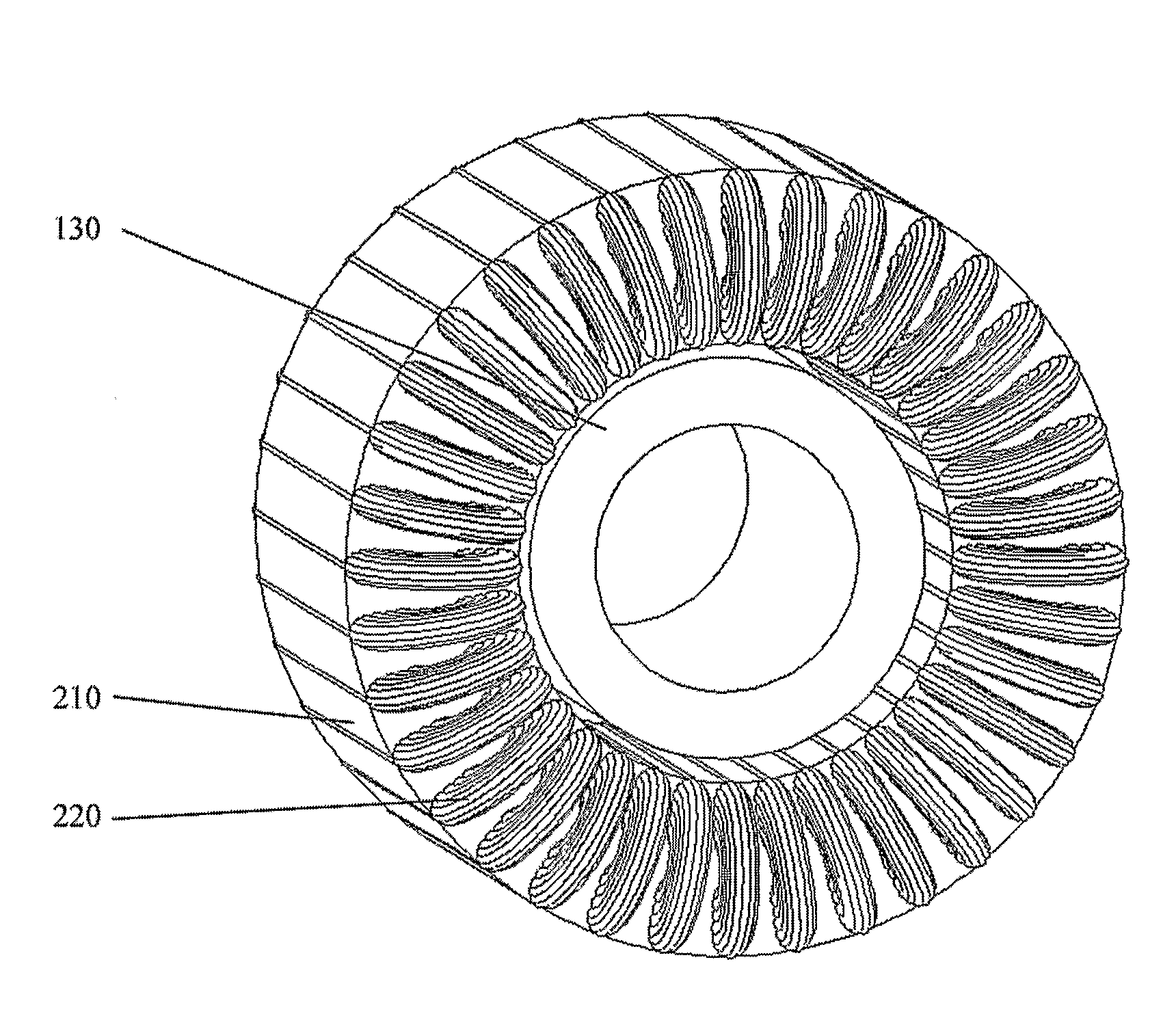
[0087]FIG. 3b shows a schematic for the present invention. The invention is directed to an outside-wound stator, in which the conductor forms a loop, not via e...


PUM


Abstract

The present invention is an electrical rotating apparatus comprising stator coils wound around the inside and outside of the stator. In a further embodiment, the machine contains a high number of phases, greater than three. In a further embodiment, the phases are connected in a mesh connection. In a further embodiment, each half-phase is independently driven to enable second harmonic drive for an impedance effect. Improvements are apparent in efficiency and packing density.

Description

TECHNICAL FIELD[0001]This invention is related to electrical rotating apparatus.BACKGROUND ART[0002]Alternating current induction motors have been developed as suitable power driving sources. Polyphase motors, including three phase motors, are widely applied in industrial and similar heavy duty applications. A rotor is rotatably mounted within an annular stator. The stator is wound with N distinct phase windings, connected to an N phase alternating current power supply, where N is an integer. The rotor is normally provided with a short circuited winding which responds to the stator field to create an induced field. An N phase power supply has phase voltages and currents which are offset from each other by 360 / N electrical degrees. The N phase winding thereby develops a magnetic field which moves circumferentially about the stator and rotor. The induced field tends to align with and follow the rotating field to create a rotating force and motion of the rotor as a result of the electr...

Claims


Application Information

Patent Timeline
IPC IPC(8): H02K1/12H02K3/28
CPCH02K3/12H02K11/00H02K3/28
Inventor EDELSON, JONATHAN SIDNEY
Owner BOREALIS TECH LTD
Learn More