Light-emitting element mounting board, light-emitting element module, lighting device, display device, and traffic signal equipment

Inactive Publication Date: 2008-06-05
THE FUJIKURA CABLE WORKS LTD
View PDF15 Cites 27 Cited by
  • Summary
  • Abstract
  • Description
  • Claims
  • Application Information

AI Technical Summary

Benefits of technology

[0034]As the light-emitting element mounting board of the first aspect of the present invention adopts a configuration where a heat radiating part is provided by removing a portion of the enamel layer of the enameled board and exposing the core metal, heat radiation is improved compared to a board where the entire surface of the core metal is covered with the enamel layer. As the heat radiating part can efficiently radiate the heat emitted by the light-emitting elements in the case where light-emitting elements are mounted and lighted on this board, temperature increases of the board and light-emitting elements can be inhibited, the light emission efficiency of the light-emitting elements can be maintained at a high level, and reliability over long periods of use can be improved.
[0035]As the light-emitting element module of the present invention includes light-emitting elements mounted in the reflective cup portions of said light-emitting element mounting board of the present invention, temperature increases of the board and light-emitting elements can be inhibited, the light emission efficiency of the light-emitting elements can be maintained at a high level, and reliability over long periods of use can be improved.
[0036]According to the second aspect of the present invention, by integrally providing fins in the metal substrate, it is possible to improve the flexural rigidity of the board body on which the light-emitting elements are mounted, and to reduce the influences of thermal shrinkage. Consequently, the flatness of the cup structures and the mounting face of the light-emitting elements can be improved, and ease of mounting (mountability) and reliab

Problems solved by technology

However, the technology disclosed in Patent Document 1 is designed to prevent the effects of heat when undertaking high-density mounting of

Method used


Image

  • Light-emitting element mounting board, light-emitting element module, lighting device, display device, and traffic signal equipment
  • Light-emitting element mounting board, light-emitting element module, lighting device, display device, and traffic signal equipment
  • Light-emitting element mounting board, light-emitting element module, lighting device, display device, and traffic signal equipment

Examples


embodiments

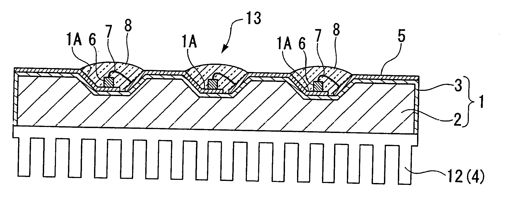
[0108]As the core metal, a low-carbon steel sheet of 100 mm length, 30 mm width and 1.5 mm thickness was used, and the reflective cup portions were formed by drill machining. Seven reflective cup portions were formed in one row at intervals of 14 mm in the lengthwise direction of the core metal, and these were formed in two rows for a total of 14. As for the dimensions of the reflective cup portions, diameter was 2 mm and depth was 0.5 mm, while the sloped parts were made at a 45 degree angle.

[0109]Next, liquid in which glass powder was mixed in a dispersion medium and uniformly dispersed was applied to the surface of said core metal, and dried, after which baking was conducted at 850 degrees centigrade (° C.) to form the enamel layer. The thickness of the enamel layer was made to be 200 micrometers (μm), copper paste was applied to the electrode formation region of the face on which the reflective cup portions were formed, and baking was conducted to form electrodes of 0.1 mm thick...

working example 1

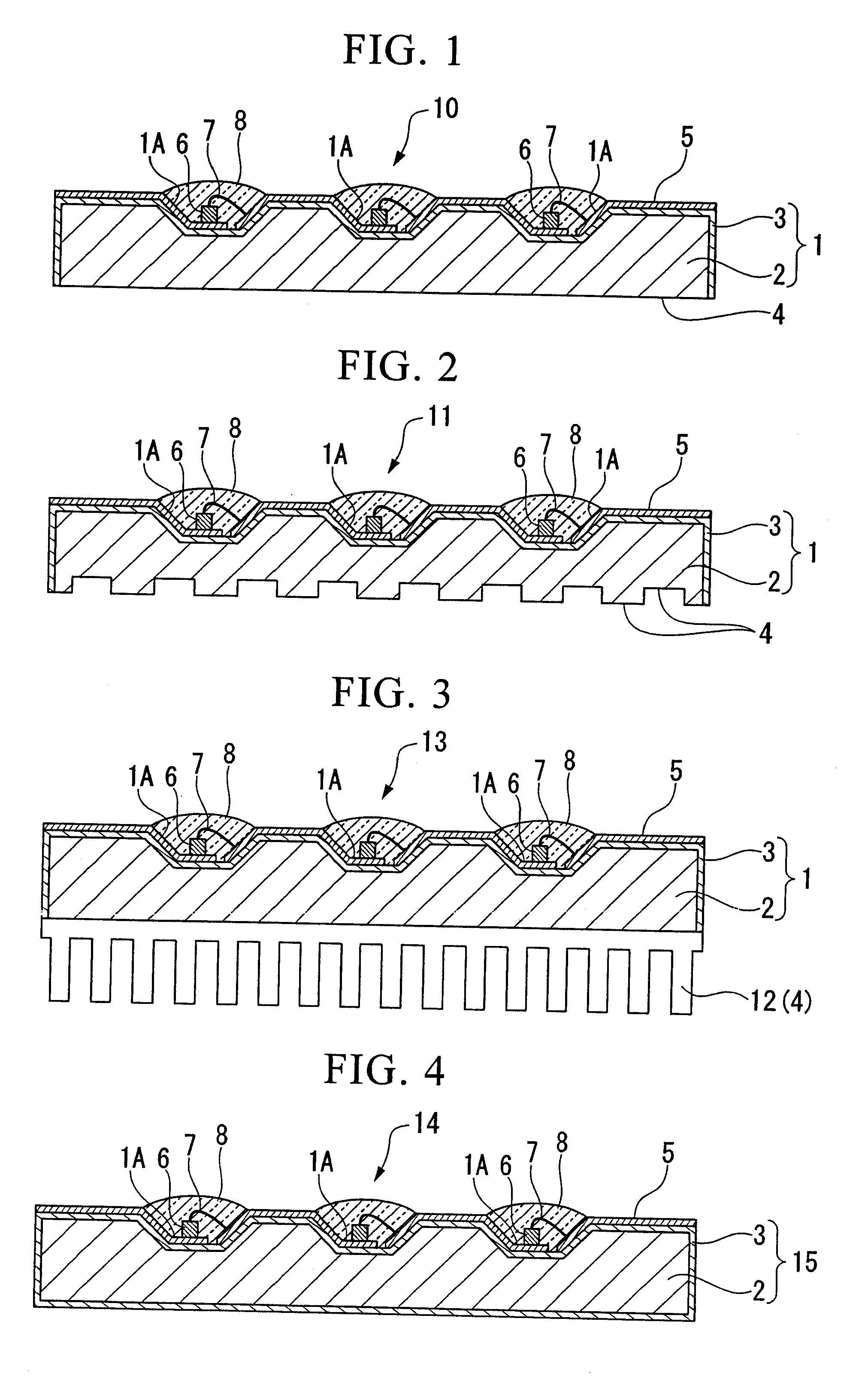
[0110]Sandblasting treatment was performed on the face of said enameled board where the reflective cup portions were not provided, the enamel layer was removed, and treatment was conducted to expose the core metal and form the heat radiating part, as shown in FIG. 1.

[0111]As the light-emitting elements, blue LED elements of 20 mW output were mounted in the reflective cup portions of this board. A total of 14 blue LED elements were mounted on said enameled board, and the reflective cup portions were sealed with silicon resin mixed with yellow light-emitting fluorescent powder, whereby white LEDs were made.

[0112]When drive current of 60 mA was made to flow into these LED elements to cause light emission, and when the central temperature of the board was measured, the temperature of the central part of the board was 130 degrees centigrade.

working example 2

[0113]Sandblasting treatment was performed on the face of said enameled board where the reflective cup portions were not provided, the enamel layer was removed, and treatment was conducted to expose the core metal. Next, face where the core metal was exposed was subjected to drill machining, holes with a diameter of 2 mm and depth of 0.2 mm were made, and a heat radiating part was formed as shown in FIG. 2 which was provided with a total of 30 indentations enlarging the surface area of the portion where the core metal was exposed.

[0114]As shown in FIG. 2, blue LED elements of 20 mW output were mounted in the reflective cup portions. A total of 14 LED elements were mounted on the enameled board, and the reflective cup portions were sealed with silicon resin mixed with yellow light-emitting fluorescent material, whereby a white LED module was made. When current of 60 mA was made to flow into each LED element to cause light emission, and when the central temperature of the board was me...


PUM


Abstract

In accordance with the present invention, a light-emitting element mounting board is provided including an enamel layer which covers the surface of a core metal, wherein reflective cup portions for mounting light-emitting elements are provided on one face of the board, and wherein a heat radiating part is formed by at least partially removing the enamel layer on the other face of the board, and exposing the core metal. Further, a light-emitting element module including light-emitting elements mounted thereon, a lighting device including the light-emitting element, a display device, and traffic signal equipment are provided.

Description

TECHNICAL FIELD[0001]The present invention relates to a light-emitting element mounting board for mounting multiple light-emitting elements such as light-emitting diodes (hereinafter “LEDs”). In particular, it relates to a light-emitting element mounting board capable of assuring satisfactory heat radiation in the case of high-density mounting of light-emitting elements in applications such as lighting; to a light-emitting element module including the light-emitting elements mounted on the board; and to lighting devices, display devices and traffic signal equipments which include the light-emitting element modules.BACKGROUND ART[0002]In recent years, LEDs have begun to be used as light sources in lighting applications. As disposition of numerous LEDs and inputs of large amounts of electric power are necessary for use in lighting applications, high-thermal-radiation LED-mounting boards are required.[0003]Conventional LED modules for mounting LEDs on LED-mounting boards adopt a config...

Claims


Application Information

Patent Timeline
IPC IPC(8): F21V7/20F21V29/00F21K99/00F21V29/505
CPCF21K9/00H05K1/021H05K1/053H05K1/183H05K3/0061H05K2201/0373H05K2201/10106H01L2224/45144H01L2224/73265H01L2224/48091H01L2924/00014H01L2924/00H01L25/0753H01L33/641H01L2924/181H01L2924/00012
Inventor TAKEMOTO, KYOSUKESUZUKI, RYUJIOHASHI, MASAKAZU
Owner THE FUJIKURA CABLE WORKS LTD
Why Eureka
Try Eureka