PC-based computing system employing a multi-GPU graphics pipeline architecture supporting multiple modes of GPU parallelization dymamically controlled while running a graphics application

a graphics pipeline and graphics application technology, applied in the field of 3d (three-dimensional) multiple graphic processing, can solve the problems of affecting the speed of each frame, the disadvantage of having each gpu render an entire frame, and the frequent jamming of the pc bus

Active Publication Date: 2008-06-12
GOOGLE LLC
View PDF99 Cites 5 Cited by
  • Summary
  • Abstract
  • Description
  • Claims
  • Application Information

AI Technical Summary

Benefits of technology

[0023]It is still another object of the present invention to provide a system and method, wherein the graphic pipeline bottlenecks of vertex processing and fragment processing are transparently and intelligently resolved.
[0024]It is still a further object of the present invention to provide a system and method that has high scalability and unlimited scene complexity.
[0025]It is still a further object of the present invention to provide a process overcoming difficulties that are imposed by the data decomposition, which is partition of data and graphic commands between GPUs.

Problems solved by technology

Both are frequently jammed over the PC bus.
It has the disadvantage of having each GPU render an entire frame.
Thus, the speed at which each frame is rendered is limited to the rendering rate of a single GPU.
While multiple GPUs enable a higher frame rate, a delay can be imparted in the response time (latency) of the system to a user's input.
With large data sets, there is another bottleneck, due to the fact that each GPU must be able to access all the data.
This requires either maintaining multiple copy operations of large data sets or possible conflicts in accessing the single copy operation.
Image division has no latency issues, but it has a similar bottleneck with large data sets, since each GPU must examine the entire database to determine which graphic elements fall within the portion of the screen allocated to said GPU.
In above applications, the data tends to be very complex, as it usually consists of massive amount of geometrical entities at the display list or vertex array.
Thus, the construction time of a single frame tends to be very long (e.g., typically 0.5 sec for 20 million polygons), which in turn slows down the overall system performance.

Method used


Image

  • PC-based computing system employing a multi-GPU graphics pipeline architecture supporting multiple modes of GPU parallelization dymamically controlled while running a graphics application
  • PC-based computing system employing a multi-GPU graphics pipeline architecture supporting multiple modes of GPU parallelization dymamically controlled while running a graphics application
  • PC-based computing system employing a multi-GPU graphics pipeline architecture supporting multiple modes of GPU parallelization dymamically controlled while running a graphics application

Examples


Embodiment Construction

The Multiple 3-D Graphic Pipeline

[0047]The current invention calls for the introduction of an extended PC graphic architecture including novel operational component, the 3-D pipeline Hub.

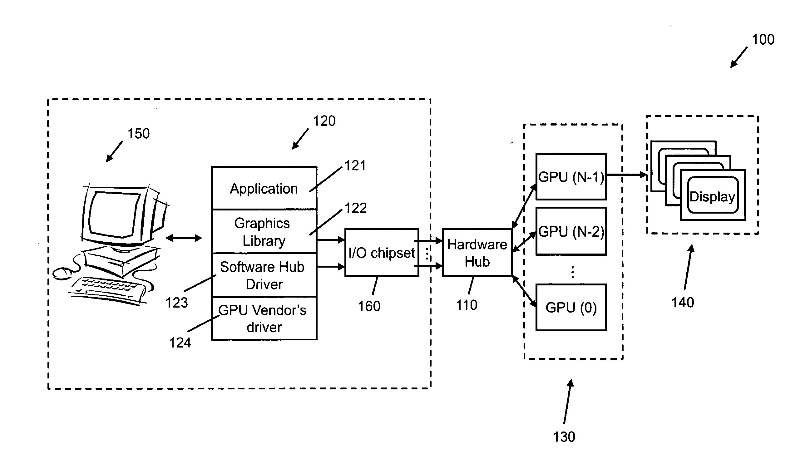
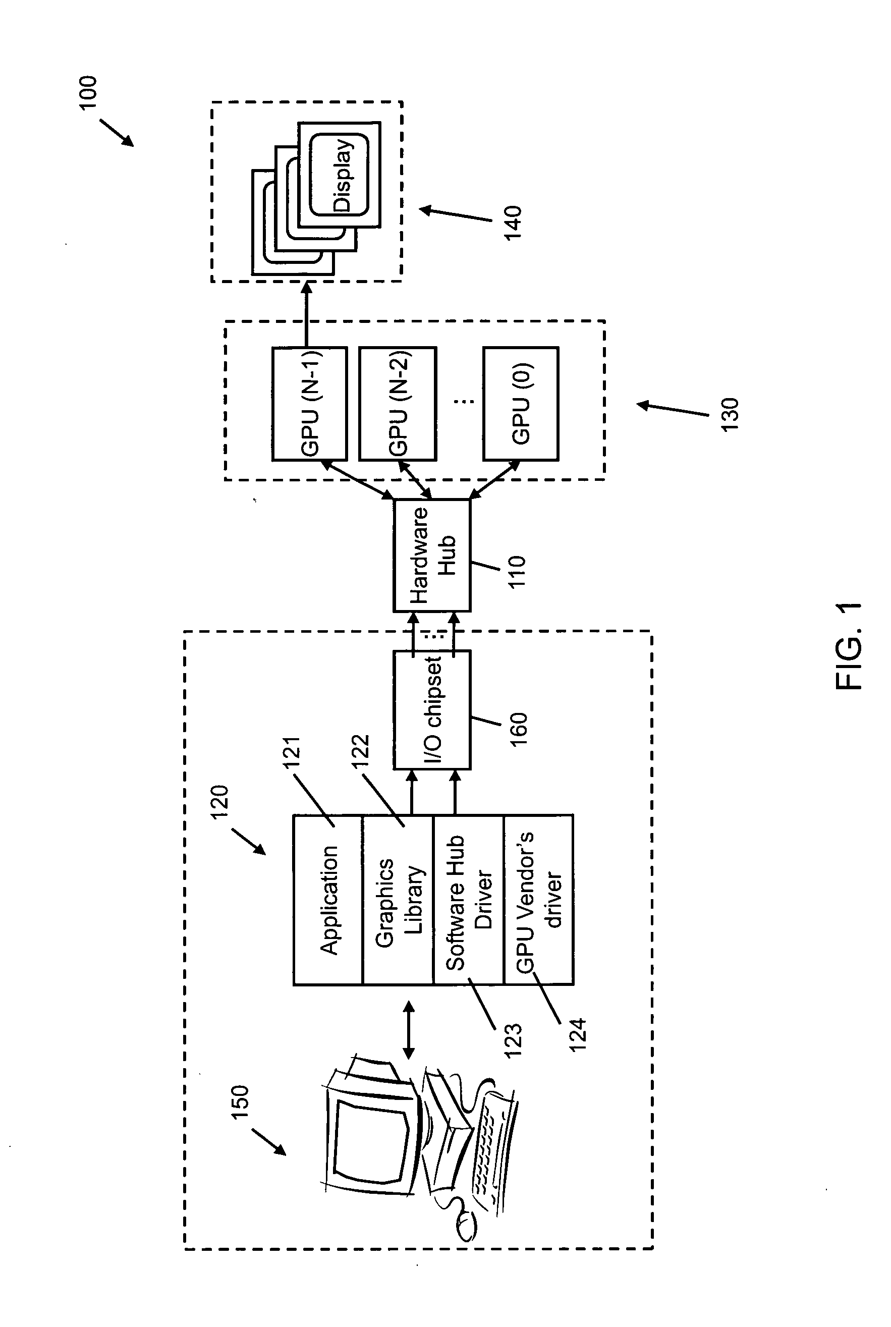
[0048]FIG. 1 presents multiple GPU architecture system 100, according to an embodiment of the present invention. The hub 110 is located in a unique position on the PC bus, between the CPU (Central Processing Unit) and a cluster of GPUs 130. The multiple graphic pipeline architecture, as described in FIG. 1, consists of Software Application 121, Graphic Library 122, Software Hub Driver 123, GPU Driver 124, Hardware Hub 110, cluster of GPUs 130, and display (s) 140. Usually, one of the GPUs is designated as a display unit. It should be noted, that it is possible to have more than one display unit, or include a display unit directly inside the Hardware Hub. A display unit can drive multiple screens, as well.

[0049]The Hub mechanism consists of a Hardware Hub component 110, located on the PC bus between ...


PUM


Abstract

A PC-based computing system capable of displaying images of 3-D objects during an interactive process between said computing system and a user thereof. The PC-based computing system includes system memory for storing software graphics applications, software drivers and graphics libraries, and an operating system (OS), stored in the system memory, and a central processing unit (CPU), for executing the OS, graphics applications, drivers. and graphics libraries. The system also includes an CPU interface module and a PC bus, a graphics processing subsystem interfaced with the CPU interface module by way of the PC bus, and a display surface for displaying said images by graphically displaying frames of pixel data produced by the graphics processing subsystem. The graphics processing subsystem includes a plurality of GPUs arranged in a parallel architecture and operating according to a parallelization mode of operation so that each GPU supports a graphics pipeline and is allowed to process data in a parallel manner. A hardware hub, interfaces with the CPU interface module and the GPUs, by way of the PC bus, and has a hub router for (i) distributing the stream of geometrical data and graphic commands among the GPUs, and (ii) transferring pixel data output from one or more of GPUs during the composition of frames of pixel data corresponding to final images for display on the display surface. The CPU interface module provides an interface between one or more software hub drivers and the hardware hub.

Description

RELATED CASES[0001]The Present application is a Continuation of copending application Ser. No. 10 / 579,682 filed May 17, 2006, which is a National Stage Entry of International Application No. PCT / IL2004 / 001069 filed Nov. 19, 2004, which is based on U.S. Provisional Application Nos. 60 / 523,084 filed Nov. 19, 2003, and 60 / 523,102 filed Nov. 19, 2003; wherein each said application is commonly owned by LUCID INFORMATION TECHNOLOGY LTD., and incorporated herein by reference in its entirety, as if set forth fully herein.BACKGROUND OF INVENTIONField of the Invention[0002]The present invention relates to a method and system for 3-D (three-dimensional) multiple graphic processing. More particularly, the invention relates to a method and system for improving the parallelization of image processing by Graphic Processing Units (GPUs), based on unified framework of three parallelization methods, which are time division, image division and object division methods.Definitions, Acronyms and Abbrevia...

Claims


Application Information

Patent Timeline
Patent Type & Authority Applications(United States)
IPC IPC(8): G06F15/00G06F15/80G06TG06T15/00
CPCG06F3/14G06F3/1438G06F9/505G09G5/363G06T15/005G06T2200/28G06T1/20
Inventor BAKALASH, REUVENREMEZ, OFFIRBAR-OR, GIGYFOGEL, EFISHAHAM, AMIR
Owner GOOGLE LLC
Why Eureka
Try Eureka