

Wireless IC device
- Summary
- Abstract
- Description
- Claims
- Application Information
AI Technical Summary
Benefits of technology
Problems solved by technology
Method used
Image

Examples
first preferred embodiment
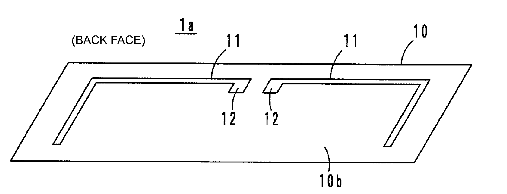
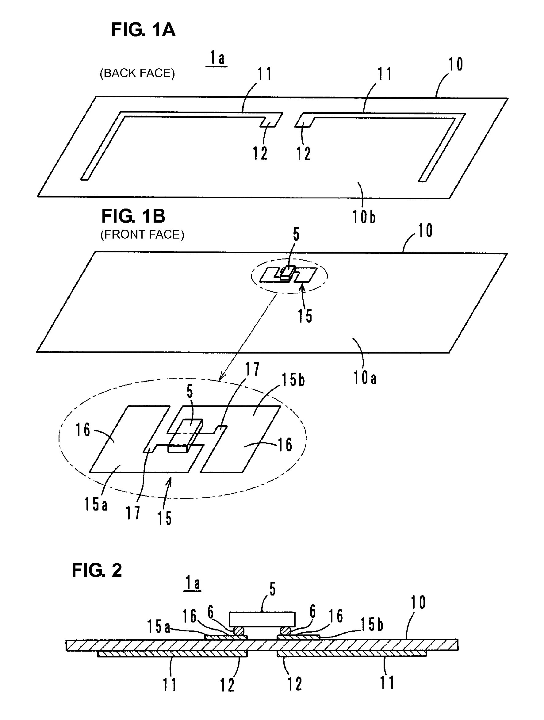
[0024]A wireless IC device 1a that is a first preferred embodiment is configured such that, as shown in FIG. 1A, radiation plates 11 are formed of a thin metal film, such as a flexible aluminum foil or metal deposition film on a second main surface (back surface) 10b of a flexible dielectric sheet 10 (for example, a resin film such as PET, or paper), and, as shown in FIG. 1B, a feeder circuit 15 is provided on a first main surface (front surface) 10a. A wireless IC chip 5 is mounted on the feeder circuit 15. FIG. 1B shows an enlarged view of the feeder circuit 15 on which the wireless IC chip 5 is mounted.
[0025]The wireless IC chip 5 is a known device which includes a clock circuit, a logic circuit, and a memory circuit, and which stores necessary information. The wireless IC chip 5 transmits and receives predetermined high frequency signals. Terminal electrodes of the wireless IC chip 5 are electrically connected to electrode patterns 15a and 15b of the feeder circuit 15 via Au bum...
second preferred embodiment
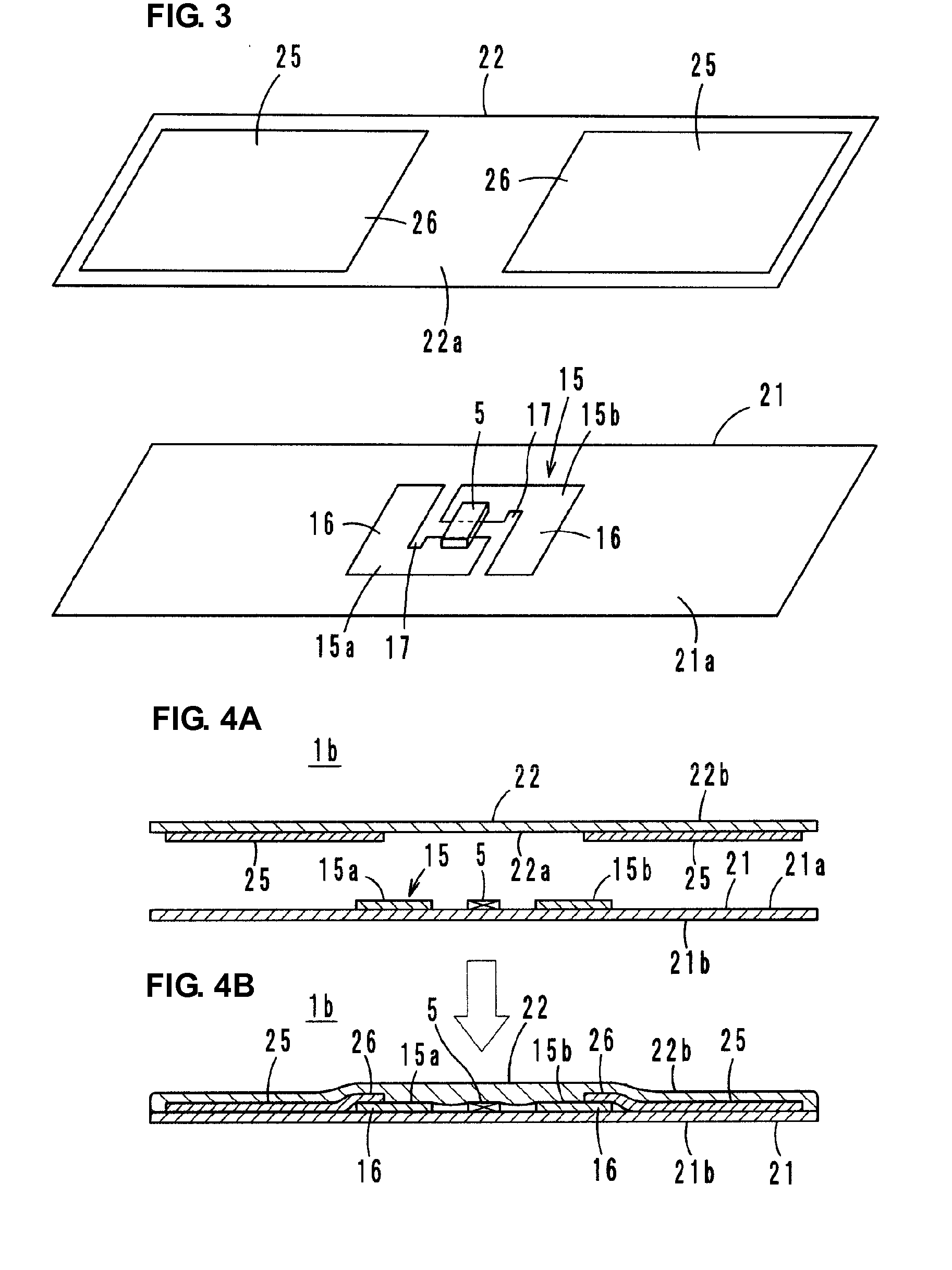
[0034]As shown in FIGS. 4A and 4B, in a wireless IC device 1b according to the second preferred embodiment, the first sheet 21 and the second sheet 22 are bonded to each other by heat bonding so that a first main surface 21a and a first main surface 22a oppose each other. Ends 16 of the feeder circuit 15 and ends 26 of the radiation plates 25 are directly, electrically coupled.
[0035]The wireless IC device 1b includes radiation plates 25 to receive a high frequency signal (for example, the UHF frequency band) radiated from a reader / writer (not shown), causes the feeder circuit 15, which is directly and electrically coupled with the radiation plates 25, to resonate, and supplies energy to the wireless IC chip 5. The wireless IC device 1b extracts predetermined energy from the received signal, and in the feeder circuit 15, matches information stored in the wireless IC chip 5 with a predetermined frequency by using the energy as a drive source. Subsequently, a transmitting signal is con...
third preferred embodiment
[0038]As shown in FIGS. 5A and 5B, in a wireless IC device 1c according to a third preferred embodiment, the first sheet 21 and the second sheet 22 are bonded to each other through an adhesive layer 29 so that a first main surface 21a and a first main surface 22a oppose each other. Ends 16 of the feeder circuit 15 and ends 26 of radiation plates 25 are capacitively coupled with each other through an adhesive layer 29 so as to oppose each other.
[0039]The wireless IC device 1c uses radiation plates 25 to receive a high frequency signal (for example, the UHF frequency band) radiated from a reader / writer (not shown), causes the feeder circuit 15 capacitively coupled with the radiation plates 25 to resonate, and supplies energy to the wireless IC chip 5. In addition, the wireless IC device 1c extracts predetermined energy from the received signal, and in the feeder circuit 15, matches information stored in the wireless IC chip 5 with a predetermined frequency by using the energy as a dri...
PUM
 Abstract
Description
Claims
Application Information