Coherent optical receiver

a receiver and optical technology, applied in the field of optical receivers, can solve the problems of difficult to realize coherent optical receivers, inability to receive, and difficulty in miniaturization, and achieve the effects of small size, simple configuration, and reduced band width for photoelectric conversion sections and the lik

Inactive Publication Date: 2008-06-19
FUJITSU LTD
View PDF9 Cites 46 Cited by
  • Summary
  • Abstract
  • Description
  • Claims
  • Application Information

AI Technical Summary

Benefits of technology

[0020]According to the abovementioned coherent optical receiver of the present invention, the intermediate frequency signals are AD converted and digital signal processing is executed, so that the optical angular frequency difference between the orthogonal polarization components of the local oscillator light can be set small. As a result, the band width required for the photoelectric conversion section and the like can be greatly reduced, and hence coherent reception is possible with a small size and simple configuration, without high speed signal light of for example 40 Gbit / s being dependent on the polarization state.

Problems solved by technology

However, in the abovementioned coherent optical reception system, there is an inherent problem in that if the polarization state of the local oscillator light output from the local oscillator light source contained in the optical receiver is orthogonal to the polarization state of the received signal light, it cannot be received.
However, in the above such conventional techniques, there is a problem in that it is difficult to realize coherent optical receivers that are small size, polarization independent, and capable of receiving very high-speed modulated signal light such as 40 Gbit / s.
That is to say, to realize the above-mentioned method of (I), an endlessly tracking automatic polarization controller is necessary, and hence miniaturization is difficult.
Furthermore, to realize the above-mentioned method of (II), a large scale light receiving front end circuit of more than twice the size is necessary, and hence miniaturization is difficult.
Moreover, to realize the abovementioned method of (III), an electronic circuit having a wide band light receiving band of more than thrice the size with respect to the signal band width is necessary, and hence it is difficult to deal with signal light of a high bit rate.
Consequently, in the conventional coherent optical receiver to which the method of (III) is applied, an electronic circuit having 3 times or more the signal band width with respect to the signal light of for example 40 Gbit / s, that is to say a band width of 120 GHz or more is necessary, and for high speed signal light of 40 Gbit / s or more, realization of this is extremely difficult.

Method used


Image

  • Coherent optical receiver
  • Coherent optical receiver
  • Coherent optical receiver

Examples


Embodiment Construction

[0032]Hereunder is a description of a best mode for carrying out the present invention, with reference to the appended drawings. Throughout all of the drawings the same reference symbols denote the same or equivalent parts.

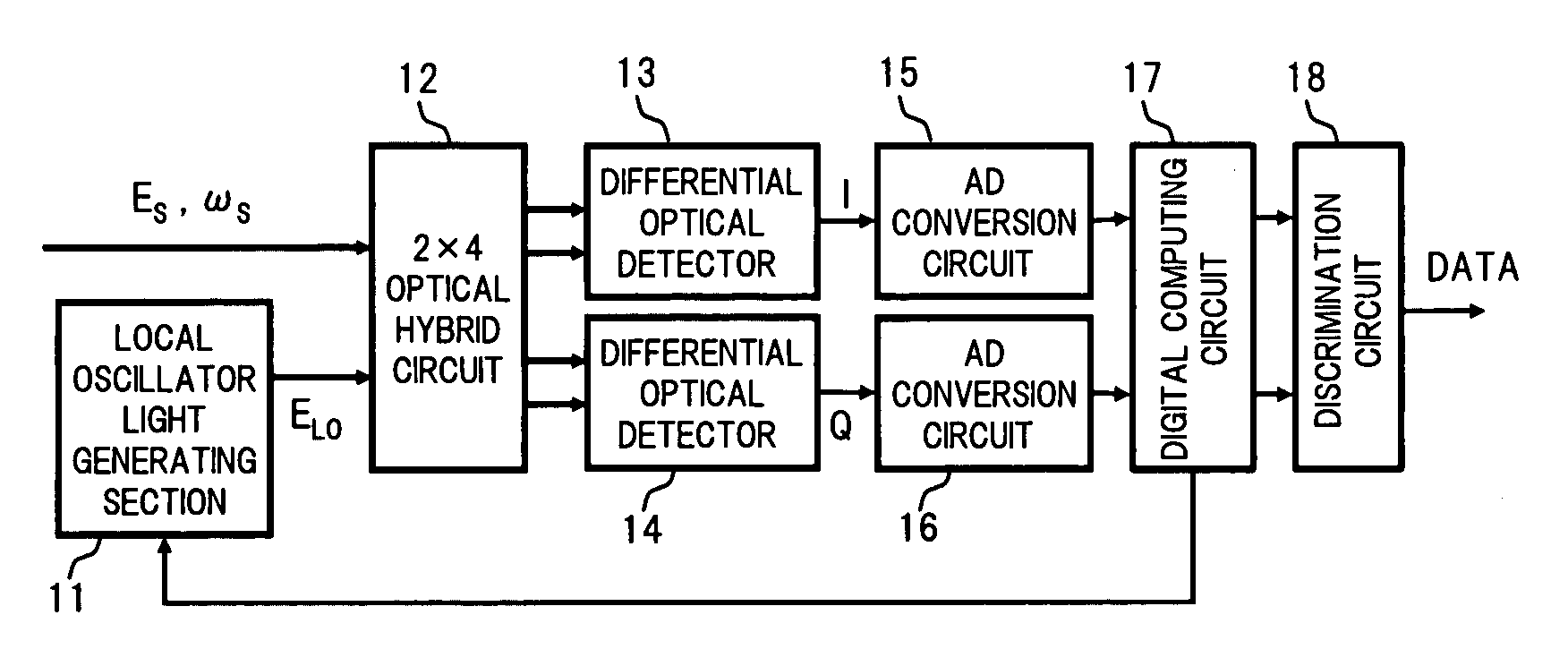
[0033]FIG. 1 is a block diagram showing a configuration of an embodiment of a coherent optical receiver according to the present invention.

[0034]In FIG. 1, the coherent optical receiver comprises for example: a local oscillator light generating section 11, a 2×4 optical hybrid circuit 12 serving as a combining section, differential optical detectors 13 and 14 serving as a photoelectric conversion section, AD conversion circuits 15 and 16 serving as an AD conversion section, a digital computing circuit 17 serving as a digital computing section, and a discrimination circuit 18 serving as a data discrimination section.

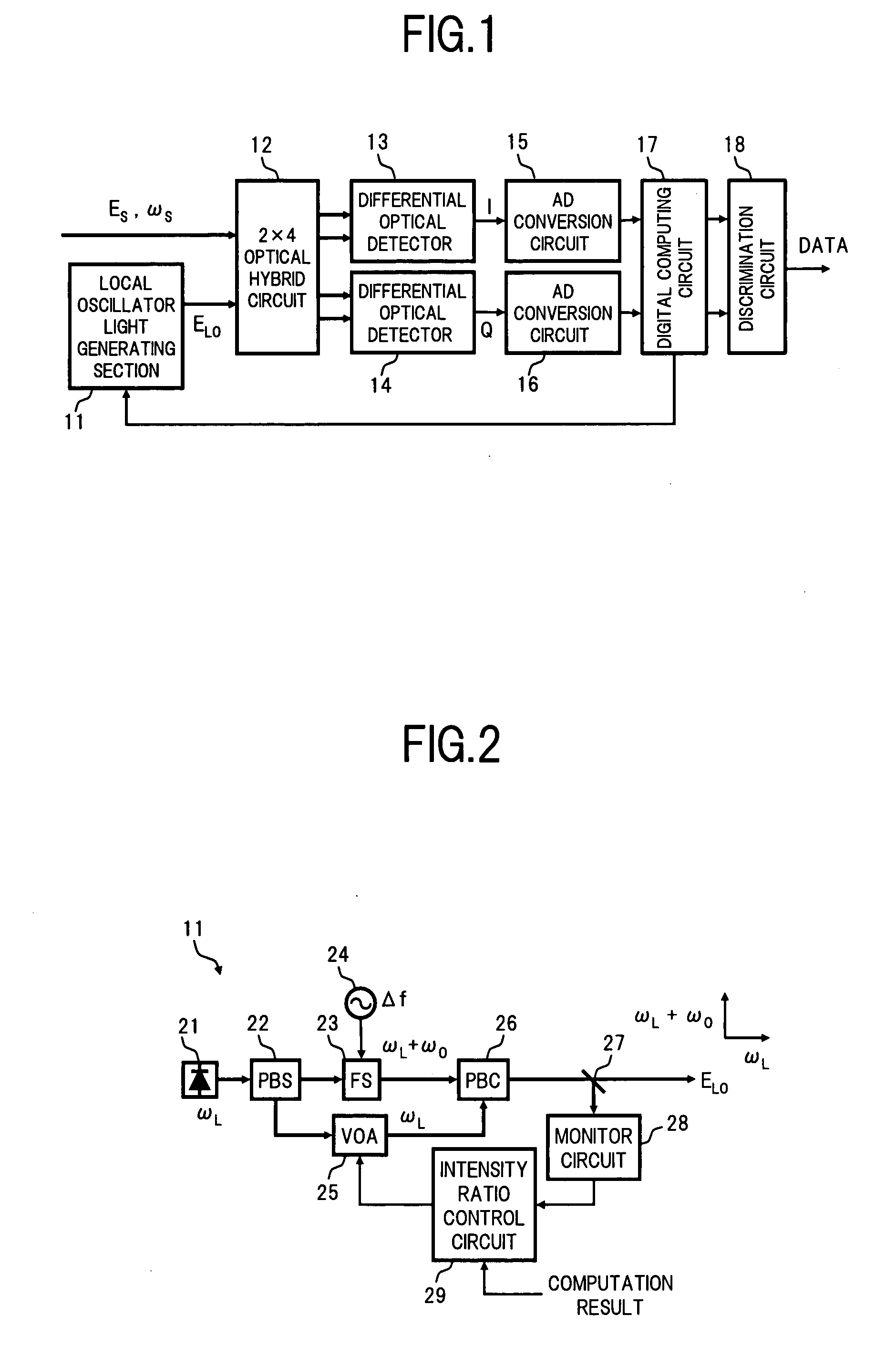
[0035]The local oscillator light generating section 11 generates a local oscillator light ELO in which a polarization component of optical angular freq...


PUM


Abstract

A coherent optical receiver of the invention combines local oscillator light having orthogonal polarization components in which the optical frequencies are different to each other, and received signal light, in an optical hybrid circuit, and then photoelectrically converts this in two differential photodetectors. Then this is converted to a digital signal in an AD conversion circuit, and computation processing is executed in a digital computing circuit using the digital signal, to estimate received data. At this time, the optical frequency difference between the orthogonal polarization components of the local oscillator light is set so as to be smaller than two times the signal light band width, and larger than a spectrum line width of the signal light source and the local oscillator light source. As a result, it is possible to realize a small size polarization independent coherent optical receiver that is capable of receiving high speed signal light.

Description

BACKGROUND OF THE INVENTION[0001]1. Field of the Invention[0002]The present invention relates to an optical receiver used in an optical transmission system, and in particular to an optical receiver of a coherent receiver type that does not depend on the polarization state of the signal light.[0003]2. Description of the Related Art[0004]In order to realize a super high-speed optical transmission system of 40 gigabits per second (Gbit / s) or above, a transceiver of a RZ-DQPSK (Return-to-Zero Differential Quadrature Phase Shift Keying) modulation format has been developed. From now on, it is desired to still more improve the optical noise immunity of the RZ-DQPSK transceiver, and to miniaturize the optical variable dispersion compensator that occupies a large size, by for example substituting by strong electrical signal processing. As a means for realizing this, for example it is hoped to adopt a coherent receiving method of for example a homodyne type, an intradyne type, or a heterodyn...

Claims


Application Information

Patent Timeline
Patent Type & Authority Applications(United States)
IPC IPC(8): H04B10/06H04B10/40H04B10/07H04B10/25H04B10/50H04B10/60H04B10/61
CPCH04B10/61H04B10/63H04B10/614H04B10/613
Inventor HOSHIDA, TAKESHI
Owner FUJITSU LTD
Why Eureka
Try Eureka