
Articles Comprising a Fibrous Support

a technology of fibrous support and support plate, which is applied in the direction of prosthesis, woodworking apparatus, medical preparations, etc., can solve the problems of low flux of membranes, decreased membrane flux rate during use, and reduced effect over tim

Active Publication Date: 2008-06-26
THE RES FOUND OF STATE UNIV OF NEW YORK
View PDF7 Cites 355 Cited by
  • Summary
  • Abstract
  • Description
  • Claims
  • Application Information

AI Technical Summary

Benefits of technology

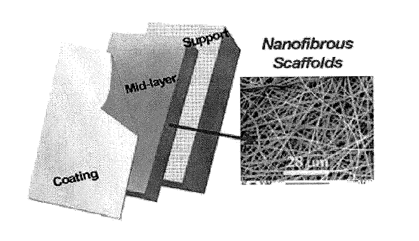
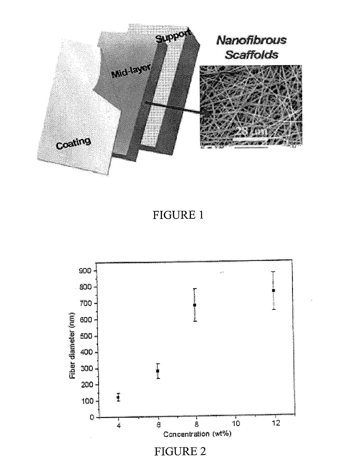
[0015]In another embodiment, the present invention is directed to an article comprising a fibrous support comprising nanofibers, and an interfacially polymerized polymer layer disposed on the surface of the fibrous support, wherein the fibrous support is in the form of a sh...

Problems solved by technology

Although the commercially available NF, UF, and RO membranes and membrane systems are effective in removing impurities such as small particles, (bio)macromolecules, oily microemulsions, and salts, these membranes often suffer from low flux due to limited permeability.
In addition, as the pores of the membranes become clogged (fouled), the flux rate of the membrane decreases during use, making them less and less effective over time.
However, a major drawback in conventional composite membranes prepared by interfacial polymerization processes is pore blockage in the microporous membrane support when it is soaked in aqueous amine solutions.
The blocked pores tend to increase the effective coating thickness of the interfacially polymerized coating layer, and consequently tend to decrease the permeate flux.
Also, the chemical nature of polyamide coating (e.g. hydrolyzed acyl halide; carboxylate groups and terminating amine groups), make interfacially polyamide composite membranes more prone to fouling by charged solute species, which also tends to significantly reduce the permeate flux.

Method used


Image

  • Articles Comprising a Fibrous Support
  • Articles Comprising a Fibrous Support
  • Articles Comprising a Fibrous Support

Examples


example 1

Top Layer Prepared by Chitosan Solution Casting

Materials and Preparation

[0107]Polyacrylonitrile (PAN) with a weight-average molecular weight (Mw) of about 1.5×10⁵ g / mol and chitosan with a viscosity-based molecular weight (Mv) ranging between 1.9×10⁵ and 3.1×10⁵ g / mol were purchased from the Aldrich Chemicals. Dimethylformamide (DMF, Aldrich) and acetic acid (glacial, Fischer) were used as solvents for PAN and chitosan, respectively, without further purification. The poly(ethylene terephathalate) non-woven substrate (PET microfilter FO2413 with an average fiber diameter of about 10 mm) for membrane support was kindly provided by Freudenberg Nonwovens (Hopkinsville, Ky.).

[0108]PAN was dissolved in DMF at 50° C. and the solution was stirred for about one day, or until the solution became homogenous. Polymer solutions of several different concentrations were prepared, ranging from 4 to 12 wt %. Chitosan was purified before use by the following procedure. The chitosan sample (˜1 g) was ...

example 3

Top Layer Prepared by PVA Solution Casting

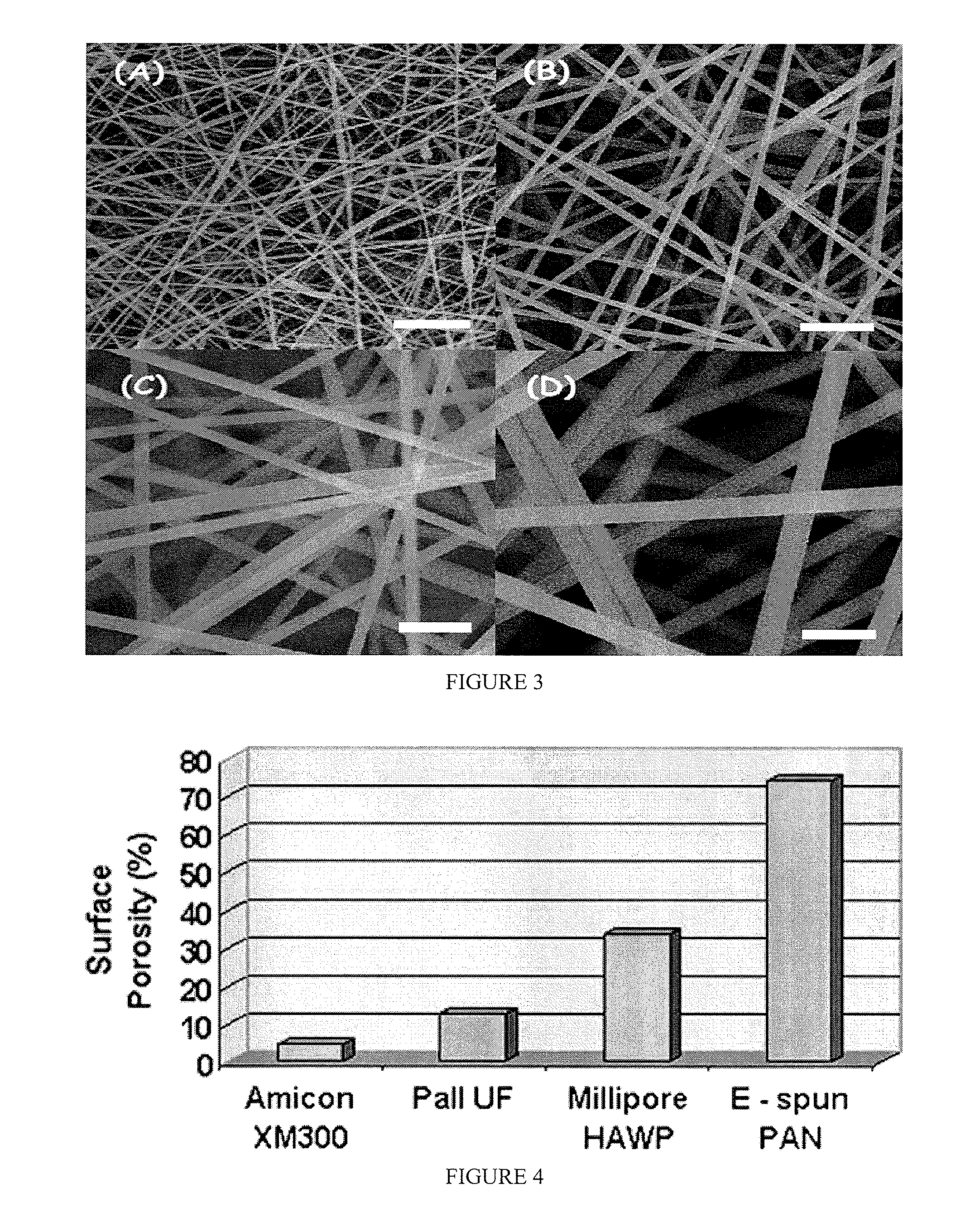
[0143]PAN electrospun fiber diameters can be controlled by varying different parameters, such as solution concentration, electric field strength, pump speed, and so on. In this example, only the concentration was changed (from 6 wt % to 12 wt %) in order to vary the fiber sizes. Fiber sizes were changed from 153 nm to 1277 nm, depending on solution concentrations (FIG. 22). The support porosity remained relatively constant (with changes of less than ˜3%) while the fiber size changed by ˜88% (FIG. 23). It was found to be desirable to minimize the fiber roughness and maintain good mechanical properties in the electrospun mid-layer in order to support a thin and flawless top-coating layer on the membrane surface. From the stress-strain curves (FIG. 24) of PAN electrospun membranes, PAN 8% showed the highest modulus and strength values, which are most appropriate for our study and were used.

[0144]Based on the PAN 8 electrospun membrane, a PVA co...


PUM

PropertyMeasurementUnit
Fractionaaaaaaaaaa
Fractionaaaaaaaaaa
Timeaaaaaaaaaa

Abstract

Articles comprising a fibrous support of nanofibers and an interfacially polymerized polymer layer disposed on a surface of the fibrous support are useful, e.g., as fluid separation membranes.

Description

CROSS-REFERENCE TO RELATED APPLICATIONS[0001]This application claims the benefit of U.S. Provisional Patent Application Nos. 60 / 873,086 filed Dec. 6, 2006 and 60 / 872,891 filed Dec. 5, 2006, the entire disclosures of which are herein incorporated by reference in their entirety for all purposes.GOVERNMENT RIGHTS[0002]This invention was made with Government support under the Office of Naval Research, grant number N000140310932. The Government has certain rights in the invention.FIELD OF THE INVENTION[0003]The present invention relates to articles comprising a fibrous support comprising nanofibers and an interfacially polymerized polymer layer disposed on the surface of the fibrous support. Articles of the present invention are useful as fluid separation membranes such as ultrafiltration membranes, nanofiltration membranes, reverse osmosis membranes, and forward osmosis membranes.BACKGROUND OF THE INVENTION[0004]With the continuous decline of available freshwater supplies, the recycling...

Claims


Application Information

Patent Timeline
IPC IPC(8): B01D71/06B29C39/00B29D31/00B01D71/10H05B6/00B29D99/00
CPCA61L15/425A61L27/56D01D5/0084B01D69/10B01D69/125A61L2400/12B01D67/00412B01D69/1071B01D69/1251B01D69/1216B01D69/107
Inventor CHU, BENJAMINHSIAO, BENJAMINYOON, KYUNGHWAN
Owner THE RES FOUND OF STATE UNIV OF NEW YORK
Learn More