Voltage Controlled Oscillator and Frequency Control Method of the Voltage Controlled Oscillator

a voltage control and oscillator technology, applied in the direction of oscillation generators, resonance circuit tuning, modulation, etc., can solve the problems of circuit complexity, cross-coupled voltage control oscillators cannot perform multi-band operation, and cannot operate at a plurality of bit rates

Active Publication Date: 2008-06-26
NEC CORP
View PDF2 Cites 13 Cited by
  • Summary
  • Abstract
  • Description
  • Claims
  • Application Information

AI Technical Summary

Benefits of technology

[0032]Therefore, a voltage controlled oscillator, which can perform multi-band operations and which can provide a plurality of continuous input / output characteristics across a wider bandwidth by being implemented using a simple configuration, can be achieved.

Problems solved by technology

That is, these cross-coupled voltage controlled oscillators can not perform a multi-band operation, because they perform a single band operation.
Further, when these cross-coupled voltage controlled oscillators are used in a clock and data recovery (CDR) circuit etc. employed for optical communication systems etc, their operation at a plurality of bit rates can not be carried out.
However, because a capacitance bank including a plurality of capacitances and a plurality of switches is necessary for this cross-coupled voltage controlled oscillator, the circuit becomes complex.
Therefore, it is difficult to provide a multi-band operation especially in a very high frequency band such as a millimeter-wave frequency band by using this cross-coupled voltage controlled oscillator.
However, because the variable inductor is usually formed by technologies such as MEMS (Micro Electro Mechanical Systems), this cross-coupled voltage controlled oscillator becomes complex in structure and in the production process.
Therefore, this cross-coupled voltage controlled oscillator is unsuitable, especially in a very high frequency band such as a millimeter-wave frequency band.

Method used


Image

  • Voltage Controlled Oscillator and Frequency Control Method of the Voltage Controlled Oscillator
  • Voltage Controlled Oscillator and Frequency Control Method of the Voltage Controlled Oscillator
  • Voltage Controlled Oscillator and Frequency Control Method of the Voltage Controlled Oscillator

Examples


first exemplary embodiment

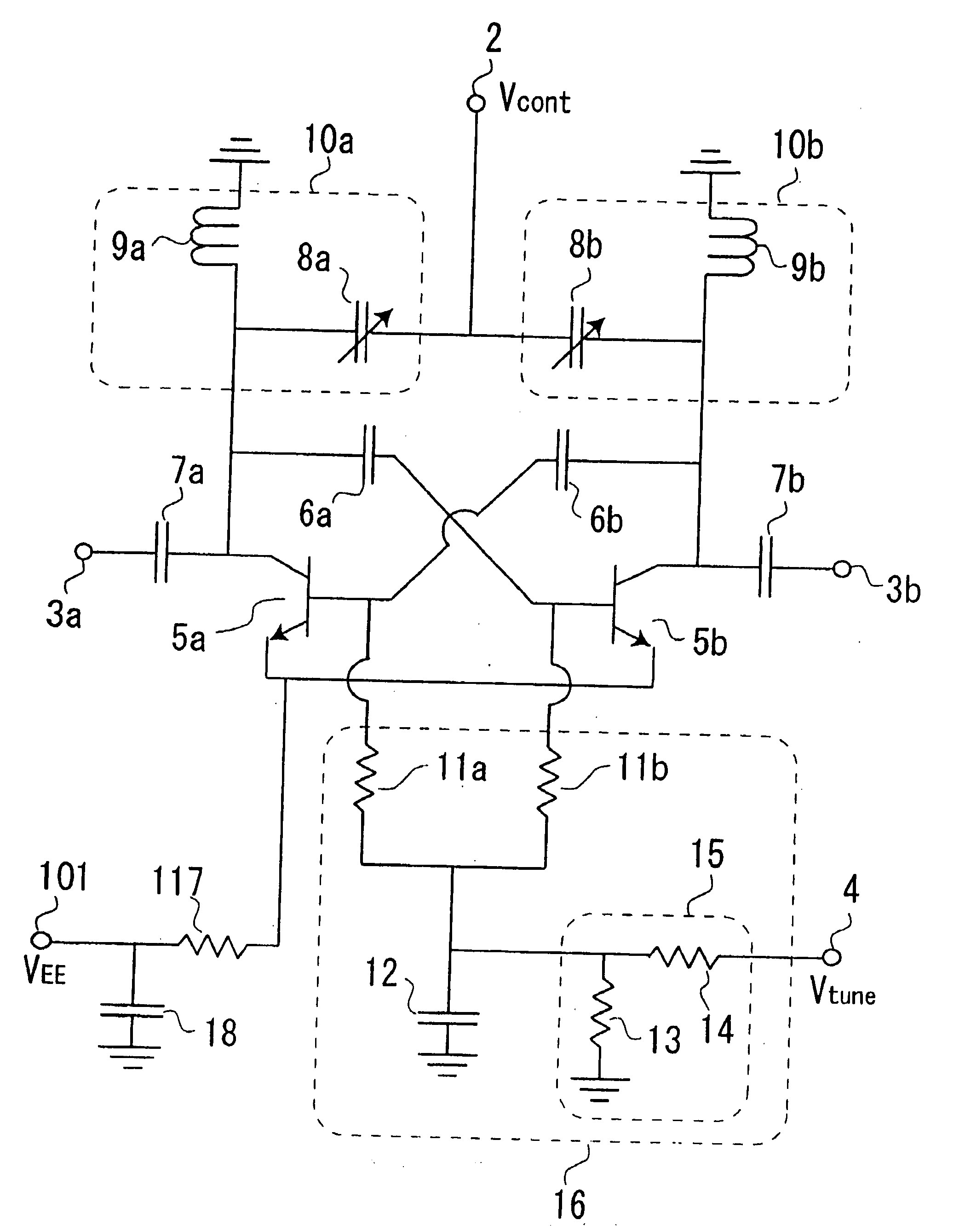
[0055]FIG. 10 is a circuit diagram illustrating a configuration of a cross-coupled voltage controlled oscillator according to a first exemplary embodiment.

[0056]Referring to FIG. 10, the cross-coupled voltage controlled oscillator of this exemplary embodiment includes power supply terminal 101 to which negative power supply voltage VEE is supplied, control terminal 2 to which control voltage Vcont for controlling an oscillation frequency is supplied, output terminals 3a, 3b for outputting a signal having the oscillation frequency variably controlled, cross-coupled transistors 5a, 5b whose collector terminals and base terminals are connected to each other in a cross-coupled arrangement, direct current blocking capacitances 6a, 6b, 7a, 7b for blocking a direct current, LC tanks 10a, 10b as a resonant circuit, resistor 117 for connecting emitter terminals of cross-coupled transistors 5a, 5b to power supply terminal 101, grounding capacitance 18 for grounding power supply terminal 101 a...

second exemplary embodiment

[0070]FIG. 11 is a circuit diagram illustrating a configuration of a cross-coupled voltage controlled oscillator according to a second exemplary embodiment. In addition, in FIG. 11, the same part as in the first exemplary embodiment shown in FIG. 10 is denoted by the same symbol.

[0071]Referring to FIG. 11, the cross-coupled voltage controlled oscillator of the exemplary embodiment has inductors 9a, 9b of the cross-coupled voltage controlled oscillator shown in FIG. 10 replaced with transmission lines 19a, 19b. In a very high frequency band in which it is difficult for a spiral inductor etc. to be formed accurately, a method by which an inductor component is formed of a transmission line in such way is suitable.

[0072]Now, operation of the cross-coupled voltage controlled oscillator of this exemplary embodiment will be hereinafter described using the simulation result. In the simulation, assuming that the cross-coupled voltage controlled oscillator of the exemplary embodiment is appli...

third exemplary embodiment

[0080]FIG. 15 is a circuit diagram illustrating a configuration of a cross-coupled voltage controlled oscillator according to a third exemplary embodiment. In addition, in FIG. 15, the same part as in the first exemplary embodiment shown in FIG. 10 is denoted by the same symbol.

[0081]Referring to FIG. 15, the cross-coupled voltage controlled oscillator of this exemplary embodiment has resistors 11a, 11b of the cross-coupled voltage controlled oscillator shown in FIG. 10 replaced with transmission lines 20a, 20b. Here, transmission lines 20a, 20b have an electric length of a ¼ wavelength at any frequency within a predetermined oscillation frequency range and desirably, they have the electric length of a ¼ wavelength at the center frequency within a predetermined output frequency range. Such configuration may avoid use of a resistor with a large value, and may sometime bring an advantage in phase noise or a change in power supply voltage at the power supply terminal.


PUM


Abstract

A voltage controlled oscillator of the present invention includes power supply terminal (101), control terminal (2) for controlling an output frequency, output terminals (3a, 3b), cross-coupled transistors (5a, 5b), capacitances (6a, 6b, 7a, 7b), LC tanks (10a, 10b), resistor (117), grounding capacitance (18) and center frequency control circuit (16). Center frequency control circuit (16) includes resistors (11a, 11b), grounding capacitance (12), center frequency control terminal (4) for controlling a center frequency of the output frequency, and voltage-divider circuit (15). Resistors (11a, 11b) are connected to the base terminals of cross-coupled transistors (5a, 5b), the other ends of resistors (11a, 11b) are connected to each other, and, to this connecting point, one end of grounding capacitance (12) and one end of voltage-divider circuit (15) are connected. The other end of voltage-divider circuit (15) is connected to center frequency control terminal (4).

Description

TECHNICAL FIELD[0001]The present invention relates to a voltage controlled oscillator (VCO) and a frequency control method of the voltage controlled oscillator, and particularly to a cross-coupled voltage controlled oscillator used in a microwave or millimeter-wave frequency band and a frequency control method of the voltage controlled oscillator.BACKGROUND ART[0002]Conventionally, in a microwave or millimeter-wave frequency band, a cross-coupled voltage controlled oscillator is used. The cross-coupled voltage controlled oscillator is a circuit which changes an oscillation frequency by controlling a voltage supplied to a control terminal. The cross-coupled voltage controlled oscillator, generally, includes a power supply terminal and a control terminal. To the power supply terminal, a fixed voltage is supplied, and to the control terminal, a control voltage for controlling the oscillation frequency is supplied.[0003]Now, a conventional cross-coupled voltage controlled oscillator wil...

Claims


Application Information

Patent Timeline
Patent Type & Authority Applications(United States)
IPC IPC(8): H03B5/12
CPCH03B2201/025H03J2200/10H03B5/1231H03B5/1293H03B5/1215H03B5/1265H03B5/124H03B5/1212
Inventor HOSOYA, KENICHIWADA, SHIGEKI
Owner NEC CORP
Why Eureka
Try Eureka