Hybrid Carbon Fiber Spun Yarn and Hybrid Carbon Fiber Spun Yarn Fabric Using the Same

a hybrid carbon fiber and spun yarn technology, applied in the direction of sustainable manufacturing/processing, final product manufacturing, electrochemical generators, etc., can solve the problems of small aperture ratio (porosity), and poor contact with catalyst layers, so as to reduce adhesion and improve the uniformity of fineness , the effect of high tensile strength

Active Publication Date: 2008-06-26
KUREHA KAGAKU KOGYO KK
View PDF7 Cites 9 Cited by
  • Summary
  • Abstract
  • Description
  • Claims
  • Application Information

AI Technical Summary

Benefits of technology

[0012]The present invention was made in consideration of the problems of the conventional technology described above. It is an object of the present invention to provide a hybrid carbon fiber spun yarn having a high tensile strength without leading to a decrease in adhesion to a matrix material such as polymer materials, and having an excellent uniformity of fineness as well. Moreover, it is another object of the present invention to provide a carbon fiber spun yarn fabric having an excellent adhesion to a matrix material and a mechanical strength, and having an excellent uniformity of thickness as well.
[0013]As a result of extensive studies to attain the foregoing objects, the present inventors have found out a hybrid carbon fiber spun yarn capable of achieving the objects by covering a core region comprising long carbon fibers having a fiber length of 500 mm or longer as a main component, with a surrounding region comprising short carbon fibers having a fiber length of less than 500 mm as a main component, and thus have accomplished the present invention.
[0026]First, in the hybrid carbon fiber spun yarn of the present invention, a core region thereof comprises long carbon fibers having a high tensile strength as a main component, so that the hybrid carbon fiber spun yarn has a high tensile strength. More specifically, a spun yarn is a long bundle in which discontinuous fibers is connected with each other by twisting the discontinuous single fibers and intertwine them each other. Therefore, its tensile strength is maintained by the frictional force due to intertwining (contact) of the single fibers. Further, as the intertwining of the single fibers increases, a contact area of fibers increases to increase the frictional force of the fibers, and thereby strength of the fibers increases. Moreover, the fibers come to be pressed strongly each other by increasing of the twisting, and thereby the frictional force of the fibers increases to improve tensile strength of the spun yarn. Furthermore, a connecting point of the fibers decreases as the fiber length of the fibers becomes long, so that strength of the spun yarn thus obtained is improved. In the hybrid carbon fiber spun yarn of the present invention, a core region thereof comprises long carbon fibers having a fiber length of 500 mm or longer as a main component, and the outer peripheral surface of the core region is covered with short carbon fibers having a fiber length of less than 500 mm. The present inventors suppose that the present invention, therefore, makes it possible to attain the above described high tensile strength.
[0028]Furthermore, in the hybrid carbon fiber spun yarn of the present invention, the core region comprises the long carbon fibers having a high tensile strength and a uniformity of fineness, and the core region is twisted together with the short carbon fibers forming the surrounding region, and thereby tensile strength of the hybrid carbon fiber spun yarn of the present invention is stronger than that of a spun yarn which is formed by the short carbon fibers alone. Moreover, it is possible to shorten a fiber length of the carbon fiber forming the surrounding region. The present inventors suppose that the present invention, therefore, makes it possible to sufficiently prevent generation of a massive part such as so-called slab and fly, in the hybrid spun yarn.
[0029]The hybrid carbon fiber spun yarn fabric of the present invention is obtained by using the above described hybrid carbon fiber spun yarn having an excellent adhesion to a matrix material and a high tensile strength, and an excellent uniformity of fineness as well, so that the hybrid carbon fiber spun yarn fabric of the present invention has an excellent adhesion to a matrix material and an excellent mechanical strength, and an excellent uniformity of thickness as well. Moreover, in the hybrid carbon fiber spun yarn fabric of the present invention, the hybrid carbon fiber spun yarns forming the fabric do not bring into close contact with each other for the presence of the surface fluffs in the surrounding region, so that a suitable aperture ratio (porosity) as for the fabric is maintained. The present inventors suppose that the present invention, therefore, makes it possible to produce the hybrid carbon fiber spun yarn fabric having an excellent permeability to gases.
[0030]According to the present invention, it is possible to provide a hybrid carbon fiber spun yarn having a high tensile strength without leading to a decrease in adhesion to a matrix material such as polymer materials, and having an excellent uniformity of fineness as well. Moreover, according to the present invention, it is possible to provide a hybrid carbon fiber spun yarn fabric having an excellent adhesion to a matrix material and an excellent mechanical strength, and having an excellent uniformity of thickness as well.

Problems solved by technology

However, when a too-rough porous body is used as the gas diffuser, contact with the catalyst layer becomes poor, so that a problem with electric power collection is occurred.
Moreover, for the filament fabric in which single yarns are aligned, there is a problem that the aperture ratio (porosity) is small and the gas permeability is low.
However, it is difficult to weave a fabric using the PAN-based spun yarns of flame-resistant because the strength thereof decreases extremely when they are heat-treated at 900° C. Therefore, if the method of weaving a fabric using the flame-resistant fibers, and then heat-treating the resultant fabric at a temperature of 900° C. is not adopted, the objective fabric cannot be obtained.
However, in that case, there has been a fault that strength of the resultant fabric lowered due to the fiber distortion by heat-treatment and the strength decrease of the spun yarn by heat-treatment.
Moreover, if a carbon fiber having a long fiber length such as a PAN-based continuousness carbon fiber is used, there is a problem that the adhesion of the resultant spun yarn to a matrix material is inferior.
However, in the carbon fiber spun yarns described in document 1 and document 2, tensile strength thereof is low.
For this reason, the gas diffusers fabric comprising them have a problem of an inevitable decrease of electric power collection ability due to a reason that the particulate fluororesin which is a binder or the carbon layer is used to improve tensile strength of the resultant carbon fiber fabric.
However, in the carbon fiber spun yarns thus obtained, the tensile strength thereof is in a range of around 0.08 to 0.09 N / tex, and it is not enough yet.
However, carbon fiber spun yarns having a sufficient tensile strength as well as a low fineness fluctuation cannot be commercially available.
Therefore, fabrics woven using commercially available carbon fiber spun yarns are not enough in the point of strength and the thickness fluctuation.

Method used


Image

  • Hybrid Carbon Fiber Spun Yarn and Hybrid Carbon Fiber Spun Yarn Fabric Using the Same
  • Hybrid Carbon Fiber Spun Yarn and Hybrid Carbon Fiber Spun Yarn Fabric Using the Same
  • Hybrid Carbon Fiber Spun Yarn and Hybrid Carbon Fiber Spun Yarn Fabric Using the Same

Examples


manufacturing example 1

Manufacturing a Pitch-Based Isotropic Carbon Fiber Bundle of 660 Tex, Heat-Treated at a Heat Temperature of 1000° C.

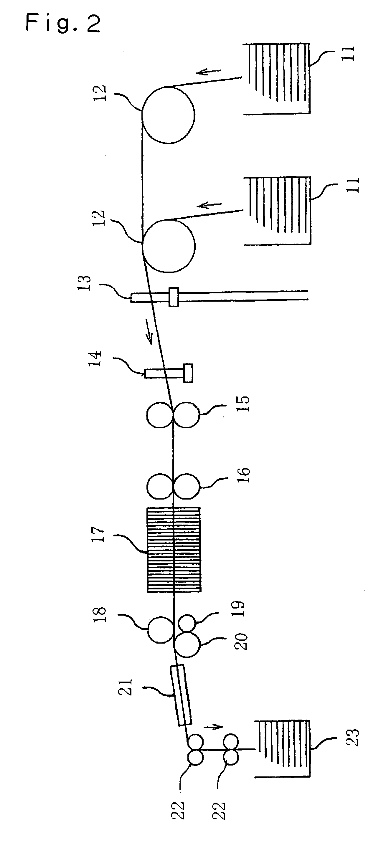
[0079]Pitch-based isotropic carbon fiber bundles (“KRECA Tow T-101S” made by KUREHA CORPORATION, 23 g / m) were used. In a drawing process using four drawing machines which were each assembled as shown in FIG. 2, two carbon fiber bundles of this type were combined together and drafted to 4.0 times with the first drawing machine to form a single carbon fiber bundle. Subsequently, two carbon fiber bundles of this type were combined together and drafted to 5.3 times with the second drawing machine to form a single carbon fiber bundle. Further, two carbon fiber bundles of this type were combined together and drafted to 5.3 times with the third drawing machine to form a single carbon fiber bundle. Moreover, two carbon fiber bundles of this type were combined together and drafted to 5.0 times with the fourth drawing machine to form a single pitch-based isotropic carbon fiber b...

manufacturing example 2

Manufacturing a Pitch-Based Isotropic Carbon Fiber Bundle of 920 Tex, Heat-Treated at a Heat Temperature of 1000° C.

[0080]Pitch-based isotropic carbon fiber bundles (“KRECA Tow T-101S” made by KUREHA CORPORATION, 23 g / m) were used. In a drawing process using four drawing machines which were each assembled as shown in FIG. 2, two carbon fiber bundles of this type were combined together and drafted to 5.0 times with the first drawing machine to form a single carbon fiber bundle. Subsequently, two carbon fiber bundles of this type were combined together and drafted to 5.0 times with the second drawing machine to form a single carbon fiber bundle. Further, two carbon fiber bundles of this type were combined together and drafted to 4.0 times with the third drawing machine to form a single carbon fiber bundle. Moreover, two carbon fiber bundles of this type were combined together and drafted to 4.0 times with the fourth drawing machine to form a single pitch-based isotropic carbon fiber b...

manufacturing example 3

Manufacturing a Pitch-Based Isotropic Carbon Fiber Bundle of 398 Tex, Heat-Treated at a Heat Temperature of 1000° C.

[0081]Pitch-based isotropic carbon fiber bundles (“KRECA Tow T-101S” made by KUREHA CORPORATION, 23 g / m) were used. In a drawing process using four drawing machines which were each assembled as shown in FIG. 2, a single carbon fiber bundle of this type was drafted to 5.0 times with the first drawing machine to form a single carbon fiber bundle. Subsequently, two carbon fiber bundles of this type were combined together and drafted to 5.0 times with the second drawing machine to form a single carbon fiber bundle. Further, two carbon fiber bundles of this type were combined together and drafted to 4.3 times with the third drawing machine to form a single carbon fiber bundle. Moreover, two carbon fiber bundles of this type were combined together and drafted to 4.3 times with the fourth drawing machine to form a single pitch-based isotropic carbon fiber bundle of 0.398 g / m ...


PUM

PropertyMeasurementUnit
lengthaaaaaaaaaa
lengthaaaaaaaaaa
densityaaaaaaaaaa

Abstract

A hybrid carbon fiber spun yarn comprising a core region which comprises carbon fibers as a main component, and a surrounding region which comprises carbon fibers as a main component and covers an outer peripheral surface of the core region;wherein 20% by mass or more of fibers forming the core region are long carbon fibers having a fiber length of 500 mm or longer,80% by mass ormore of fibers forming the surrounding region are short carbon fibers having a fiber length of less than 500 mm, anda mass ratio between the long carbon fibers and the short carbon fibers (long carbon fibers:short carbon fibers) is in a range of 20:80 to 80:20.

Description

TECHNICAL FIELD [0001]The present invention relates to a hybrid carbon fiber spun yarn useful for a gas diffuser (a collector) for solid polymer electrolyte fuel cell, or the like, and a hybrid carbon fiber spun yarn fabric using the same.BACKGROUND OF THE INVENTION [0002]Recently, so-called PAN-based carbon fibers using polyacrylonitrile (PAN) as a starting material, so-called rayon-based carbon fibers using rayon as a starting material, and so-called pitch-based carbon fibers using pitches as a starting material are manufactured as carbon fibers. Moreover, as pitch-based carbon fibers, anisotropic carbon fibers and isotropic carbon fibers are manufactured. Among them, pitch-based isotropic carbon fibers are widely used for usages in which the characteristics such as lightness, chemical resistance, heating resistance, sliding ability and electrical conductivity are demanded, because pitch-based isotropic carbon fibers are comparatively economic due to starting material of low price...

Claims


Application Information

Patent Timeline
Patent Type & Authority Applications(United States)
IPC IPC(8): D02G3/02D02G3/22
CPCD02G3/16Y10T428/2929D03D15/00D03D15/12D10B2101/12D10B2201/24D10B2321/10D10B2401/063D10B2505/00D10B2505/02H01M8/0234Y02E60/50Y10T428/2918Y10T428/2925D02G3/36Y02P70/50D03D15/513D03D15/275D03D15/573D03D15/41D03D15/44D03D1/00
Inventor KOBAYASHI, TATSUOSONOBE, NAOHIROIWAMOTO, SHIGEKI
Owner KUREHA KAGAKU KOGYO KK
Why Eureka
Try Eureka