Method of Controlling a Rail Transport System for Conveying Bulk Materials

a rail transport system and bulk material technology, applied in the direction of vehicle position/course/altitude control, process and machine control, instruments, etc., can solve the problems of limited site specific applications of vehicles, high capital cost, limited hill climbing ability, etc., to achieve improved control, reliable determination of train location, and high speed

Active Publication Date: 2008-06-26
RAIL VEYOR TECH GLOBAL
View PDF41 Cites 34 Cited by
  • Summary
  • Abstract
  • Description
  • Claims
  • Application Information

AI Technical Summary

Benefits of technology

[0013]An embodiment of the invention, herein using the Rail-Veyor™ system by way of example, provides improved control through inter-drive station communications providing the ability of one drive station to communicate both train speed and position data to cooperating drive stations. A high speed communications network may preferably be employed. The control system of the present invention may include redundant position sensors for reliably determining a precise train location. With knowledge of the precise train location, desirably adjusting train spacing for multiple trains is accomplished with confidence and efficiency. The control system of the present invention controls the acceleration and deceleration of a train over multiple drive stations and thus permits smaller horse power drives than typically used, thus resulting in higher efficiency and lower system hardware costs.
[0014]By way of example for one embodiment in keeping with the teachings of the present invention may comprise a series of interconnected cars creating a free rolling train that forms a long open trough which may move along a light rail track in a loop from a loading point to a discharge site, and back to the loading point without stopping. This loop allows multiple trains to run on the same track. This feature significantly increases capacity by simply adding more trains without the need to add additional drive stations, thus increasing capacity at a comparably lower incremental cost.
[0015]For an embodiment herein described by way of example, each car has two rear wheels with a front and rear ball / clevis connection that allows connection of the cars thus forming the train. Each car also has horizontal drive plates on both sides, outside of the wheels, which roll on the track. A urethane flap is used to seal the gap between the cars allowing significant flexibility when the train moves over undulating terrain. Forward motion is provided by a series of opposing stationary drive stations located on either side of the train so that the train is always in contact with a drive station. Each drive station provides sufficient pressure on the side plates to prevent slipping. The drive tires are each rotated through a gear reducer and A-C electric motor. Motor speeds are controlled with a Variable Frequency Drive (VFD). Since the track between the loading point and the discharge point is continuous, multiple trains can be operating at the same time. Material is loaded on the train, transported to the unload site, discharged through a vertical outside loop, and returned to the loading site to repeat the cycle. The system is designed for continuous operation. As long as the feed bin is kept full and the discharged material is removed, Rail-Veyor™ needs no intervention from the operator.

Problems solved by technology

These vehicles, however, are limited to site specific applications and are provided at a high capital cost.
Major off road trucks have evolved that require very wide roadways for passing each other, are not energy efficient per ton-mile of material transported, have limited hill climbing ability, and are dangerous because of potential of operator error as well as being environmentally unpleasant neighbors.
Because of low friction, the use of free rolling iron or steel wheels on steel tracks they are very efficient users of energy but are limited in capacity relative to the drivers or locomotives required.
The inclination capable of conventional railroad systems is limited to the friction between the weighted drive wheels and track.
Spotting cars for both loading and unloading is time consuming and labor intensive.
Although moving from one location to another may be cost effective, the added cost of batch loading and unloading stages in shorter distance transports reduces the rail transport cost effectiveness.
Very long distance single belt runs are very capital cost intensive and are subject to catastrophic failure when a belt tears or rips, typically shutting down the entire system and dumping the carried load, requiring cleanup.
Conveyor belts are relatively energy efficient but can require high maintenance because of an inherent problem of multiple idler bearings requiring constant checking and replacement.
Because conveyor belts are very flexible and desirably operated over fairly flat terrain, they are not efficient at transporting moderately high solids slurry where water and fines can accumulate in low spots and spill over the side creating wet spilled slurry handling problems.
It has become apparent that increases in labor, energy and material costs plus environmental concerns that alternate transport methods need to be applied that are energy and labor efficient, quiet, non-polluting, and esthetically unobtrusive.

Method used


Image

  • Method of Controlling a Rail Transport System for Conveying Bulk Materials
  • Method of Controlling a Rail Transport System for Conveying Bulk Materials
  • Method of Controlling a Rail Transport System for Conveying Bulk Materials

Examples


Embodiment Construction

[0031]The present invention will now be described more fully hereinafter with reference to the accompanying drawings, in which embodiments of the invention are shown. This invention may, however, be embodied in many different forms and should not be construed as limited to the embodiments set forth herein. Rather, the embodiments herein presented are provided so that this disclosure will be thorough and complete, and will fully convey the scope of the invention to those skilled in the art.

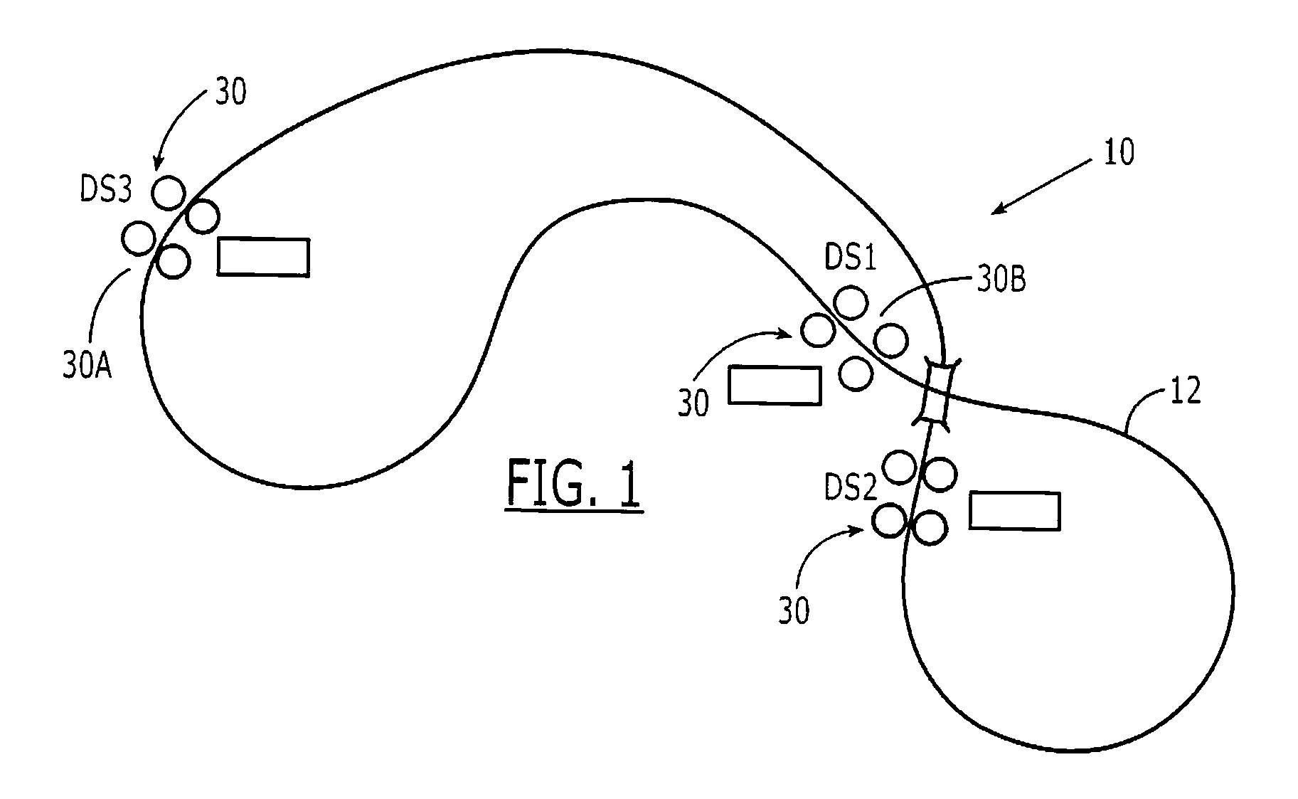
[0032]By way of example, a control system in keeping with the teachings of the present invention is herein described using the Rail-Veyor™ system. Other applications may include underground mining operations where the loaded train is stacked on top of an inverted empty return train, which reduces the horizontal profile, and an application where the train is connected in a continuous loop like a conventional conveyor without the belt tensioning problems and potential fire risks resulting from drive ...


PUM


Abstract

A train is driven by drive stations positioned along a track for frictionally contacting side plates on the train. The drive speed is controlled in response to sensors located at each drive station sensing a position of a wheel and a side plate for confirming a presence of the train. A start command is transmitted from the drive station driving the train to a second drive station downstream when a lead car is within a preselected distance from the second drive station. The drive station at the second drive station is quickly accelerated to a target speed for synchronizing the first drive station with the second drive station. After receiving the train, the second drive station then transmits a stop command to the first drive station for fast decelerating the drive station to a stop.

Description

CROSS REFERENCE TO RELATED APPLICATIONS[0001]This application claims the benefit of and priority to U.S. Provisional Patent Applications having Ser. No. 60 / 871,232 for “Method of Controlling a Rail Transport System for Bulk Materials” filed on Dec. 21, 2006 and Ser. No. 60 / 909,971 for “System and Method of Controlling a Rail System having a Train for Transporting Bulk Materials” filed on Apr. 4, 2007, the disclosures of which are herein incorporated by reference in their entirety, and commonly owned.FIELD OF THE INVENTION[0002]The present invention generally relates to system for driving a train having no internal drive, and in particular to a system and method of controlling multiple trains through a loading and unloading of bulk materials.BACKGROUND OF THE INVENTION[0003]Method and apparatus for moving bulk materials in conventional trains, trucks, conveyor belts, aerial tramways or as a slurry in a pipeline are well known and are typically used in various industries because of si...

Claims


Application Information

Patent Timeline
Patent Type & Authority Applications(United States)
IPC IPC(8): G05D13/02
CPCG05D13/62B61B13/127
Inventor DIBBLE, MERTON F.CAPERS, JOE
Owner RAIL VEYOR TECH GLOBAL
Why Eureka
Try Eureka