Hooked differential mobility spectrometry apparatus and method therefore

a technology of differential mobility and spectrometry, which is applied in the field of ion mobility spectrometry (ims) and mass spectrometry, can solve the problems of large ion loss, large beams cannot be transmitted through standard ms inlets (of either the capillary or orifice/curtain plate type) without great ion loss, and achieves improved ionization efficiency and thus analytical sensitivity, and simplified instrument design and operation. , th

Inactive Publication Date: 2008-07-03
BATTELLE MEMORIAL INST
View PDF2 Cites 25 Cited by
  • Summary
  • Abstract
  • Description
  • Claims
  • Application Information

AI Technical Summary

Benefits of technology

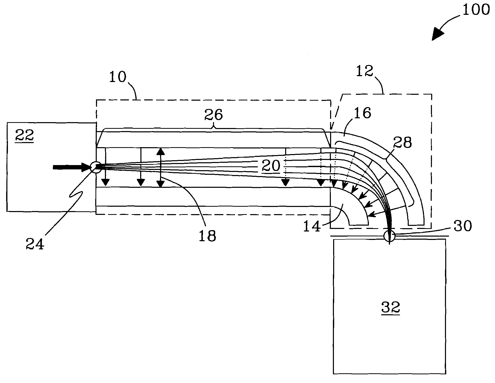
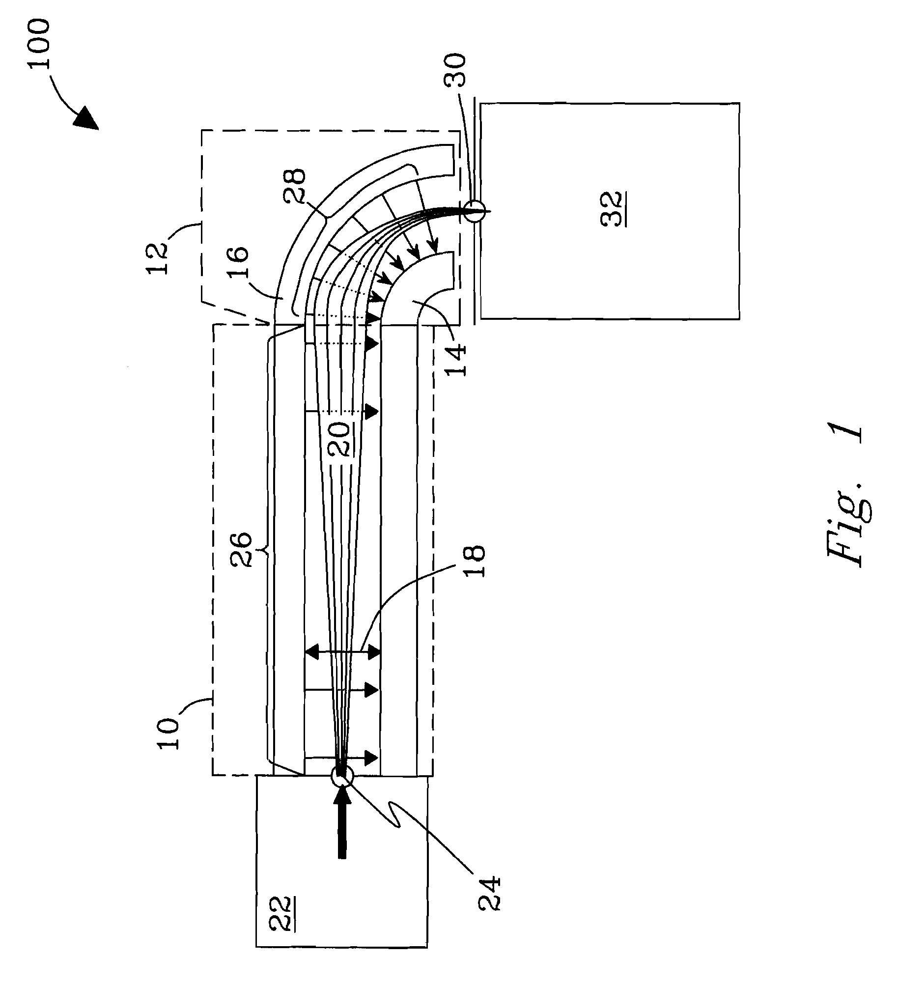
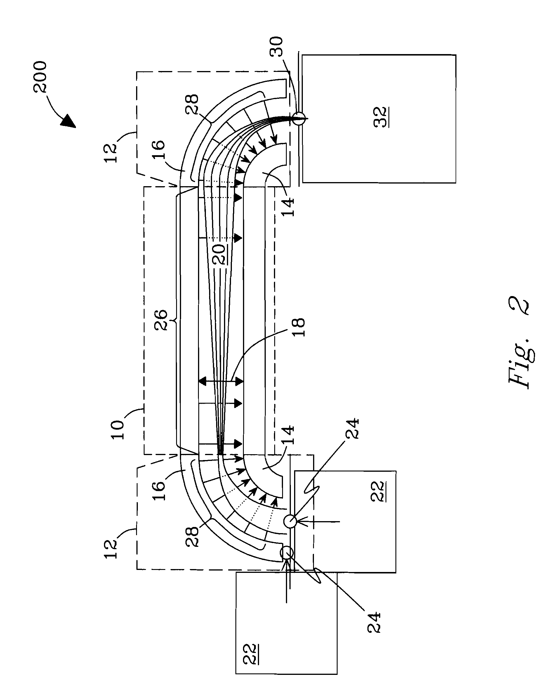
[0014]One may desire to couple multiple DMS analyzers to one subsequent instrument stage, e.g., to overcome the charge capacity limitations of a single analyzer or to improve the ionization efficiency and thus analytical sensitivity using multiple ion sources (for example, in ESI), but is not limited thereto. Hence, in an embodiment, one set of curved electrodes receives ions from two or more substantially planar DMS analyzers.
[0015]It may be advantageous to deliver ions from one ion source or instrument stage to multiple DMS analyzers, e.g., to overcome the charge capacity limitation of a single analyzer, but is not limited thereto. Hence, in another embodiment, one set of curved electrodes delivers ions to two or more substantially planar DMS analyzers.
[0016]It is desirable to reduce loss of ions both after injection into DMS and during transmission from DMS to subsequent stages. In an embodiment, the system features two curved electrode sets, one delivering ions to and the other receiving ions from one or more substantially planar DMS analyzers. In particular, two DMS analyzers could...

Problems solved by technology

However, even with the formidable power of modern MS, nearly all real-world samples require prior separations.
Such wide beams cannot be transmitted through standard MS inlets (of either the capillary or orifice/curtain plate type) without great ion losses.
Nonetheless, the slit is still much smaller than the opening of DMS gap ...

Method used


Image

  • Hooked differential mobility spectrometry apparatus and method therefore
  • Hooked differential mobility spectrometry apparatus and method therefore
  • Hooked differential mobility spectrometry apparatus and method therefore

Examples


example

[0045]To test the capability of the invention to enhance transmission of ions filtered by planar FAIMS to following stages, common MS standards were analyzed using a planar FAIMS / TOF MS system. The instrument was configured with or without the FAIMS / MS interface of the invention described above in reference to FIG. 7, including a non-contiguous “slit” aperture made of 11 circular holes 0.19 mm in diameter, all other conditions being equal. This integrated configuration is exemplary of many like systems and is intended to be illustrative, not exclusive. All such systems as will be contemplated by those of skill in the art in view of the disclosure are within the scope of the invention. No limitations are intended.

[0046]Experimental. Solutions of reserpine (5 μM and 50 μM) and bradykinin (10 μM) in 50:49:1 methanol:water:acetic acid were used. The DMS unit described hereinabove was operated using a DV voltage of 3.9 kV and a CV scan rate of 5 V / min. Ion signals measured at the MS dete...


PUM


Abstract

Disclosed are a device and method for improved interfacing of differential mobility spectrometry (DMS) or field asymmetric waveform ion mobility spectrometry (FAIMS) analyzers of substantially planar geometry to subsequent or preceding instrument stages. Interfacing is achieved using curved DMS elements, where a thick ion beam emitted by planar DMS analyzers or injected into them for ion filtering is compressed to the gap median by DMS ion focusing effect in a spatially inhomogeneous electric field. Resulting thinner beams are more effectively transmitted through necessarily constrained conductance limit apertures to subsequent instrument stages operated at a pressure lower than DMS, and/or more effectively injected into planar DMS analyzers. The technology is synergetic with slit apertures, slit aperture/ion funnels, and high-pressure ion funnel interfaces known in the art which allow for increasing cross-sectional area of MS inlets. The invention may be used in integrated analytical platforms, including, e.g., DMS/MS, LC/DMS/MS, and DMS/IMS/MS that could replace and/or enhance current LC/MS methods, e.g., for proteomics research.

Description

[0001]This invention was made with Government support under Contract DE-AC06-76RLO1830 awarded by the U.S. Department of Energy. The Government has certain rights in the invention.FIELD OF THE INVENTION[0002]The invention is in the field of ion mobility spectrometry (IMS) and mass spectrometry. More specifically, it is an apparatus and method for improved interfacing between differential mobility spectrometry (DMS) or field asymmetric waveform ion mobility spectrometry (FAIMS) analyzers and various stages of analytical instrumentation.BACKGROUND OF THE INVENTION[0003]Mass spectrometry (MS) is the core technology of state-of-the-art biological analyses, including proteomics, metabolomics, and other “omic” fields of the post-genomic era. However, even with the formidable power of modern MS, nearly all real-world samples require prior separations. Those separations had traditionally been performed in the condensed phase (liquid or solid), e.g., liquid chromatography (LC), capillary ele...

Claims


Application Information

Patent Timeline
IPC IPC(8): H01J49/06
CPCH01J49/004G01N27/624
Inventor SHVARTSBURG, ALEXANDRE A.TANG, KEQIIBRAHIM, YEHIA M.SMITH, RICHARD D.
Owner BATTELLE MEMORIAL INST
Why Eureka
Try Eureka