

Projection optical system and projection image display apparatus
a projection optical system and projection image technology, applied in the field of projection optical systems and projection image display apparatuses, can solve the problems of increasing the difficulty of manufacturing increasing the manufacturing cost, and the height of the lower portion below the screen, so as to achieve the effect of wide angle of view, easy removal of chromatic aberration, and increased size of the convex reflecting surface
- Summary
- Abstract
- Description
- Claims
- Application Information
AI Technical Summary
Benefits of technology
Problems solved by technology
Method used
Image

Examples
first embodiment
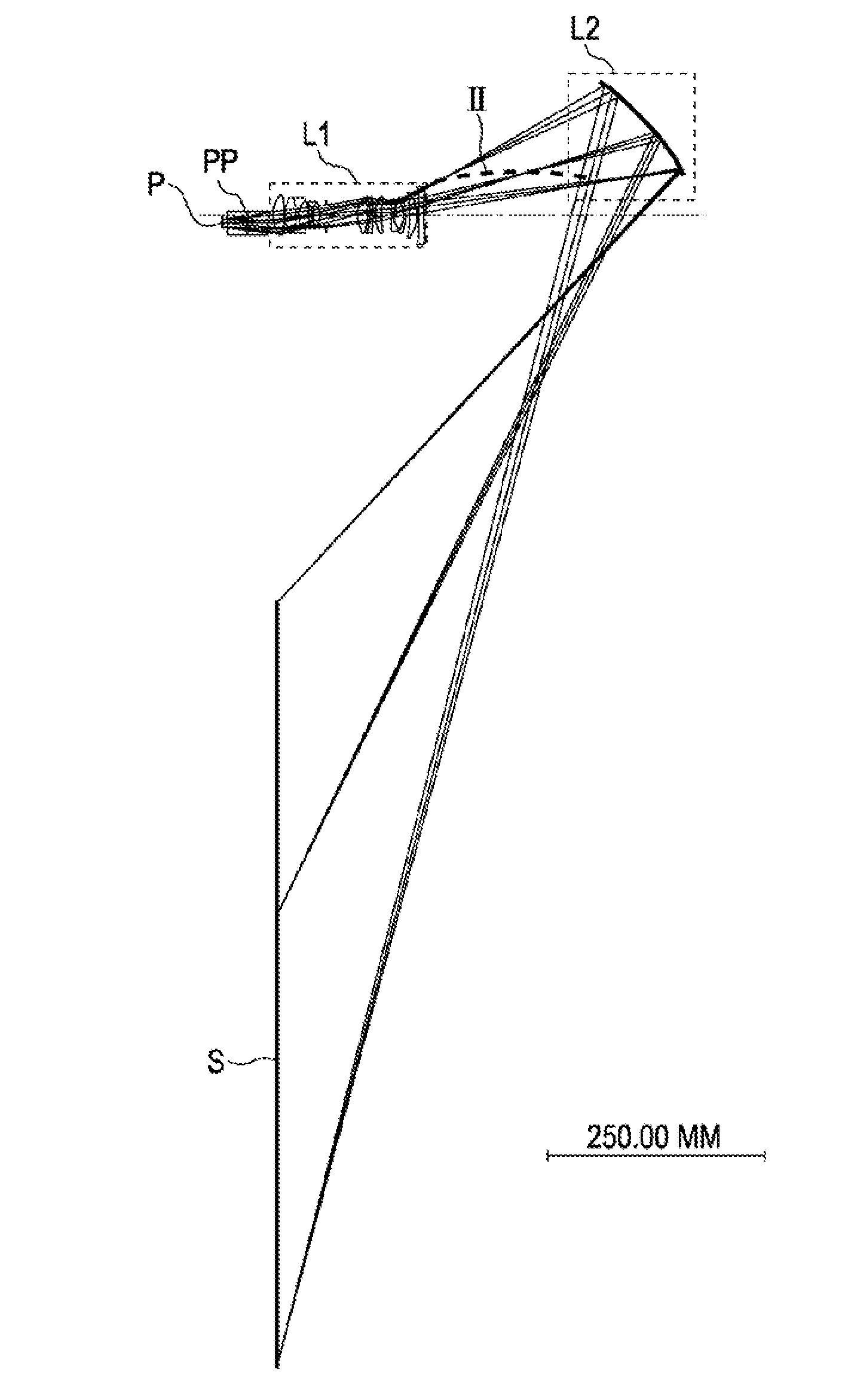
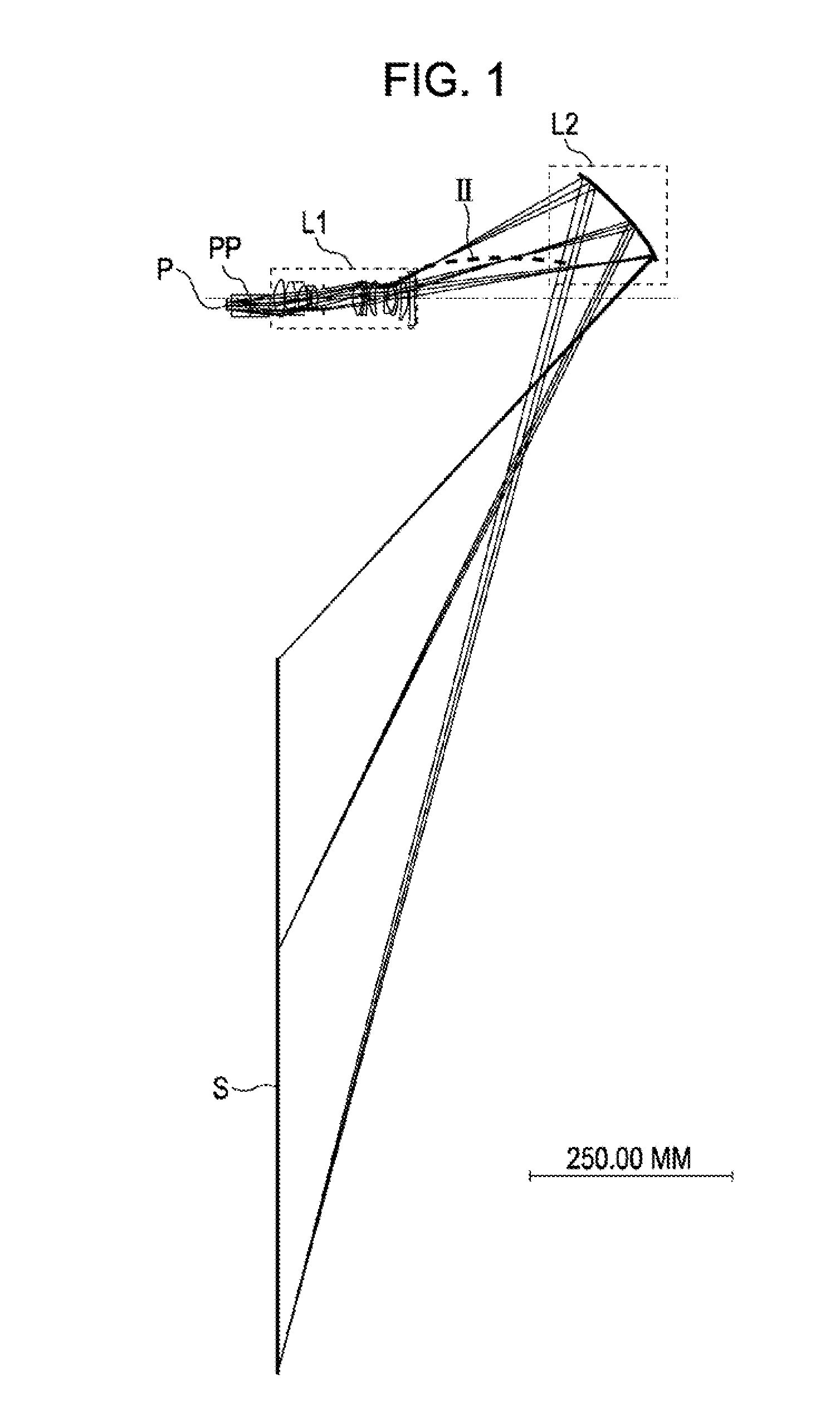
[0158]FIG. 1 illustrates a light path according to a first embodiment. An image display element P serves as a modulating unit. A light ray emitted from a light source (not shown) is modulated by the image display element P on the basis of a video signal. In this way, a primary imaging plane is formed. A reflective or transmissive dot-matrix liquid crystal display panel or a digital micromirror device (DMD) can be used for the image display element P. A reference symbol PP represents a polarizing beam splitter (PBS), a color combining prism that combines video signals of R, G, and B colors, or a total internal reflection (TIR) prism.
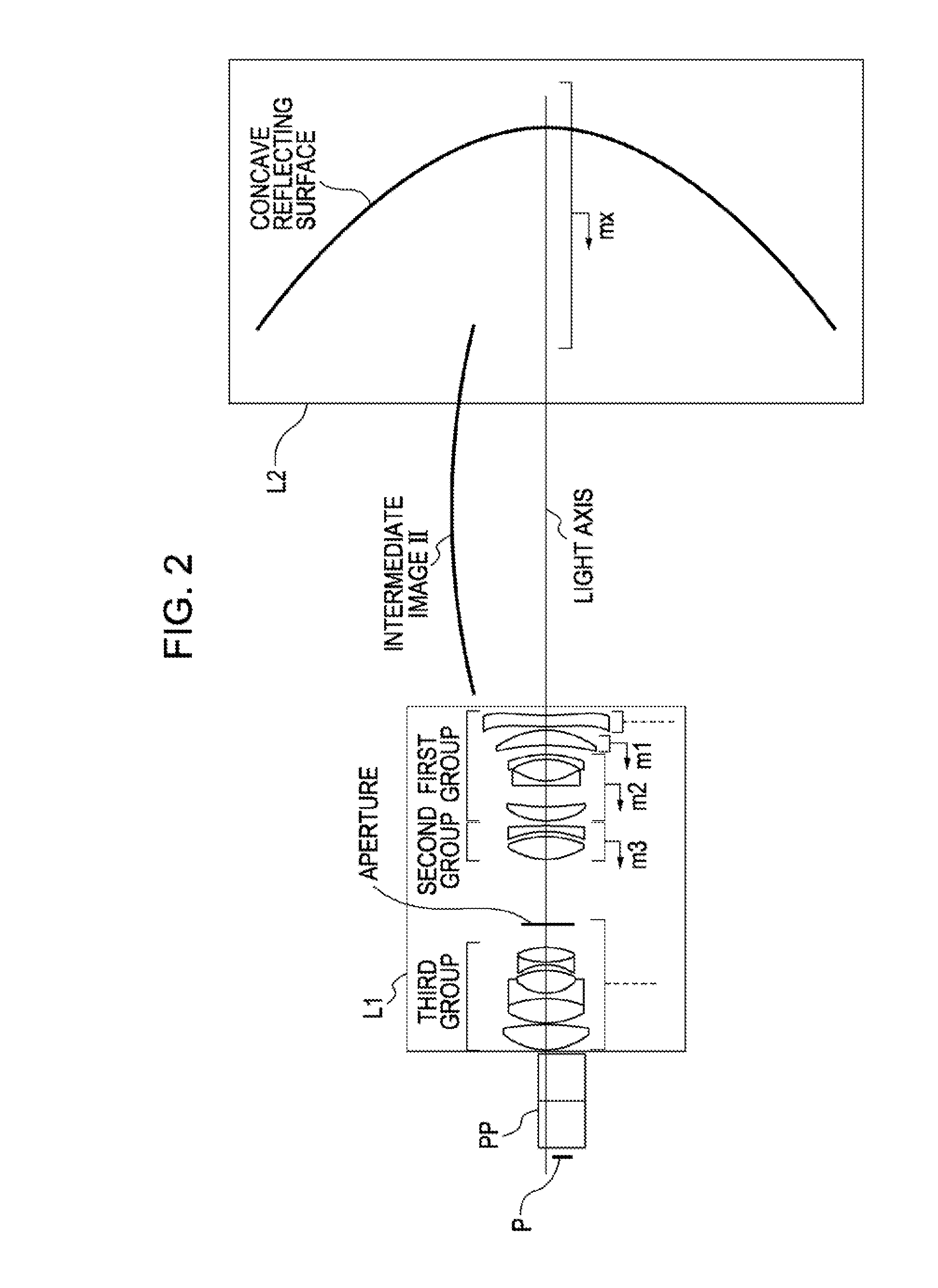
[0159]FIG. 2 illustrates a projection optical system portion shown in FIG. 1 in detail. A first optical system L1 includes a first group having a negative refractive power, a second group having a positive refractive power, an aperture, and a third group having a positive refractive power in this order from a side of the secondary imaging plane to the sid...
second embodiment
[0168]FIG. 12 illustrates a light path according to a second embodiment. An image display element P serves as a modulating unit. A light ray emitted from a light source (not shown) is modulated by the image display element P on the basis of a video signal. In this way, a primary imaging plane is formed. A reflective or transmissive dot-matrix liquid crystal display panel or a digital micromirror device (DMD) can be used for the image display element P. A reference symbol PP represents a polarizing beam splitter (PBS), a color combining prism that combines video signals of R, G, and B colors, and a total internal reflection (TIR) prism.
[0169]FIG. 13 illustrates a projection optical system portion shown in FIG. 12 in detail. A first optical system L1 includes a first group having a negative refractive power, a second group having a positive refractive power, an aperture, and a third group having a positive refractive power in this order from the side of the secondary imaging plane to ...
third embodiment
[0176]FIG. 20 illustrates a light path according to a third embodiment. An image display element P serves as a modulating unit. A light ray emitted from a light source (not shown) is modulated by the image display element P on the basis of a video signal. In this way, a primary imaging plane is formed. A reflective or transmissive dot-matrix liquid crystal display panel or a digital micromirror device (DMD) can be used for the image display element P. A reference symbol PP represents a polarizing beam splitter (PBS), a color combining prism that combines video signals of R, G, and B colors, and a total internal reflection (TIR) prism.
[0177]FIG. 21 illustrates a projection optical system portion shown in FIG. 20 in detail. A first optical system L1 includes a first group having a negative refractive power, a second group having a positive refractive power, an aperture, and a third group having a positive refractive power in this order from the secondary imaging plane side to the side...
PUM
 Abstract
Description
Claims
Application Information