Magnetic Memory and Manufacturing Method For the Same

a technology of magnetic memory and manufacturing method, which is applied in the field of magnetic memory, can solve the problems of increasing the aspect ratio inconvenient operation of the magnetic memory, and data is erroneously written, and achieves the effect of suppressing the variation in the switching field of the magnetization free layer

Active Publication Date: 2008-07-10
NEC CORP
View PDF10 Cites 80 Cited by
  • Summary
  • Abstract
  • Description
  • Claims
  • Application Information

AI Technical Summary

Benefits of technology

[0028]According to the present invention, it is possible to make the direction of the stress inducing magnetic anisotropy close to the direction of the shape magnetic anisotropy and ideally make both of them coincident and consequently suppress the variation in the switching field of the magnetization free layer.

Problems solved by technology

One of the severest problems in the magnetic memory is a variation in magnetic field for reversion of magnetization of the magnetization free layer, i.e., a switching field.
This is inconvenient for the operation of the magnetic memory.
The variation in the switching field of the magnetization free layer decreases a margin of the write current and may bring about a situation that the data is erroneously written to the non-selected memory cell.
However, the increase in the aspect ratio of the magnetization free layer is not preferable because the size of the memory cell of the magnetic memory is increased.

Method used


Image

  • Magnetic Memory and Manufacturing Method For the Same
  • Magnetic Memory and Manufacturing Method For the Same
  • Magnetic Memory and Manufacturing Method For the Same

Examples


first embodiment

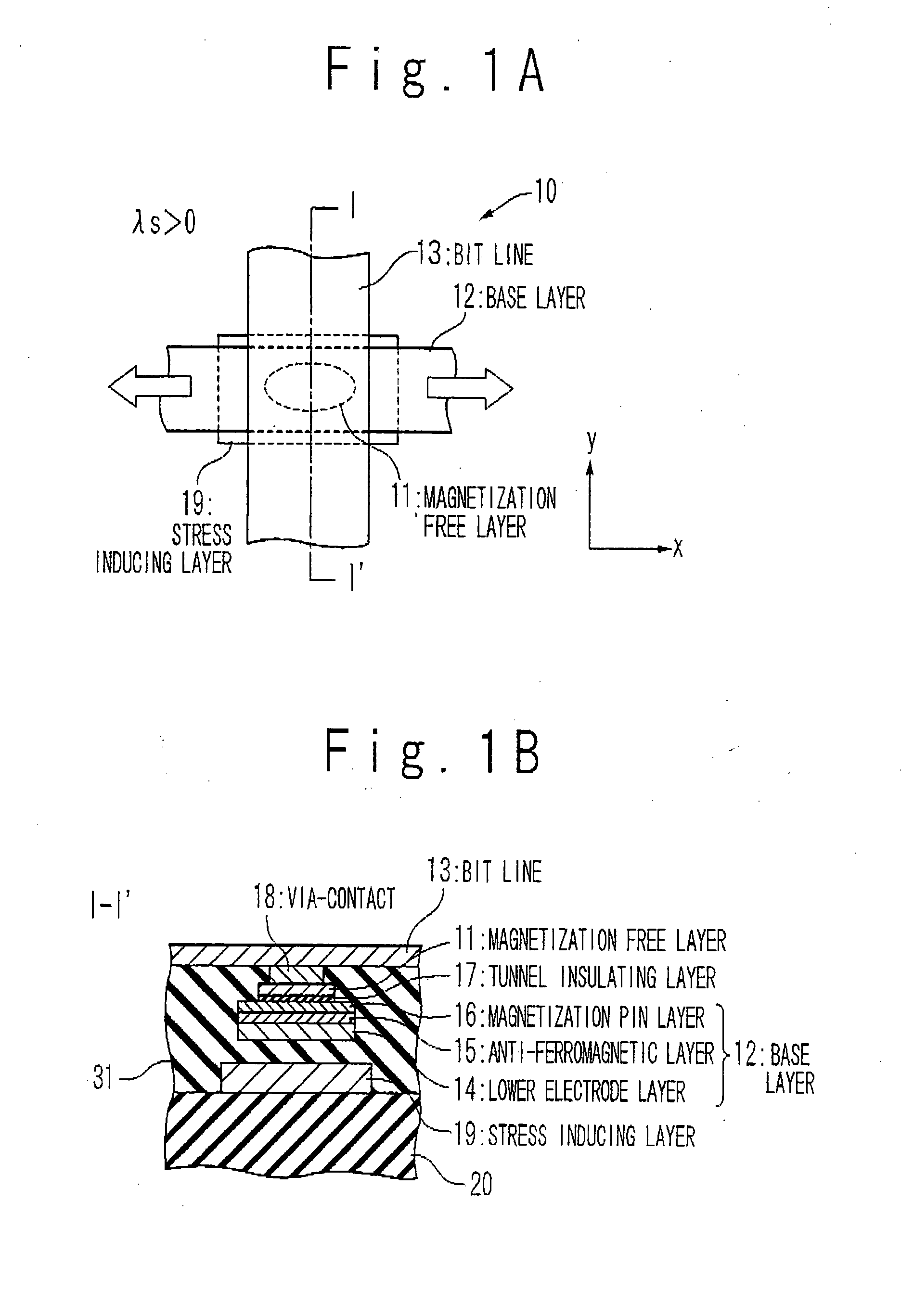
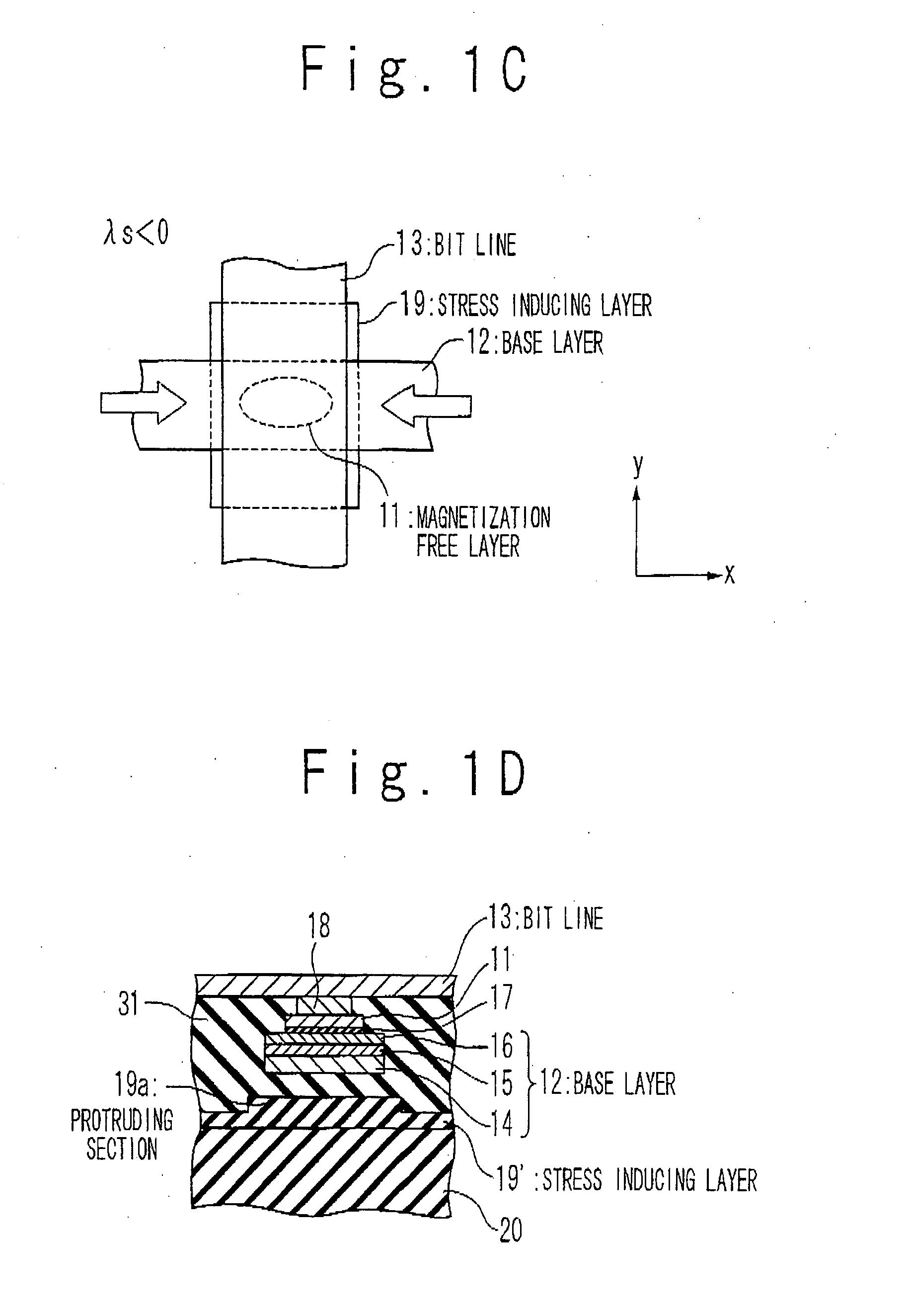
[0097]FIG. 1A is a plan view showing a configuration of a magnetic memory cell 10 of the magnetic memory according to the first embodiment of the present invention. As shown in FIG. 1A, the magnetic memory cell 10 is formed as a cross point memory array, and specifically, a memory cell contains a magnetization free layer 11 for holding a data, a base layer 12 functioning as a word line, and a bit line 13. The magnetization free layer 11 has a shape that is long in the x-axis direction, and its shape magnetic anisotropy is oriented to the x-axis direction. The base layer 12 is provided to extend in the x-axis direction, and the bit line 13 is provided to extend in the y-axis direction. The data write into the magnetization free layer 11 is performed by supplying a write current to the base layer 12 and the bit line 13.

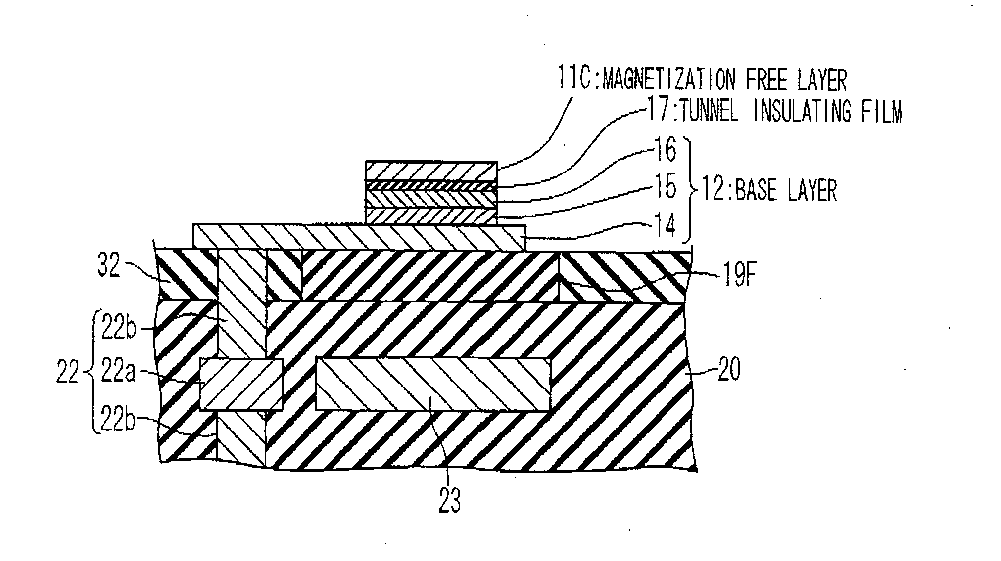
[0098]As shown in FIG. 1B, the base layer 12 includes a lower electrode layer 14, an anti-ferromagnetic layer 15 and a magnetization pinned layer 16. The anti-ferromagn...

second embodiment

[0130]The base layer serving as a lower layer for the magnetization free layer and the tunnel insulating layer can be used as the stress inducing structure for applying the stress to the magnetization free layer, through suitable selection of its inner stress and shape. The discussion with regard to the inner stress and shape of the stress inducing layer and the direction of the stress applied to the magnetization free layer can be applied to the base layer as it is. For example, when the base layer is formed such that its inner stress is compression stress and its shape is long in the y-axis direction, the tensile stress can be applied to the magnetization free layer in the x-axis direction. The second embodiment provides the structure of the magnetic memory in which the base layer is used as the stress inducing structure.

[0131]FIG. 10A is a plan view showing an example of the structure of a memory cell 10D of the magnetic memory according to the second embodiment, and FIG. 10B is ...

third embodiment

[0140]Even the wiring located lower than the base layer (namely, the wiring located between the base layer and the substrate) can be used as the stress inducing structure to apply the stress to the magnetization free layer, by suitably selecting the extension direction. As mentioned above, according to the experiment by the inventor, the wiring arranged between the base layer and the substrate applies the tensile stress to the magnetization free layer in the same direction as the extension direction of the wiring and applies the compression stress to the magnetization free layer in the direction orthogonal to the extension direction of the wiring. Using such a phenomenon, the wiring located lower than the base layer can be used as the stress inducing structure. The third embodiment provides the structure of the magnetic memory in which the wiring located lower than the base layer is used as the stress inducing structure.

[0141]FIG. 14A is a plan view showing an example of the structu...


PUM


Abstract

The present invention to provide a new technique to reduce a variation in switching field of a magnetization free layer in a magnetic memory. The magnetic memory according to the present invention includes a magnetization free layer including a ferromagnetic layer having a shape magnetic anisotropy in a first direction and a magnetic strain constant is positive; and a stress inducing structure configured to apply a tensile stress to said magnetization free layer in a same direction as the first direction.

Description

TECHNICAL FIELD[0001]The present invention relates to a magnetic memory, and more particularly relates to a magnetic memory, which is designed such that a data is written into a magnetization free layer by a current flowing through a write wiring.BACKGROUND ART[0002]A magnetic memory that uses a spontaneous magnetization (herein after, to be merely referred to as “magnetization”) of a ferromagnetic to store a data is one of nonvolatile memory devices to which the greatest attention has been paid in recent years. As a memory cell of the magnetic memory, for example, as disclosed in U.S. Pat. No. 5,650,958, a magnetic resistance element composed of two ferromagnetic layers is used which are separated by a non-magnetic layer of an conductor or insulator. One of the ferromagnetic layers of the two layers is designed such that the orientation of the magnetization is easily changed by an external magnetic field, and the other is designed such that the orientation of the magnetization is n...

Claims


Application Information

Patent Timeline
Patent Type & Authority Applications(United States)
IPC IPC(8): H01L27/00
CPCG11C11/16H01L43/08H01L27/222G11C11/1675G11C11/161G11C11/1659H10B61/00H10N50/10
Inventor FUKUMOTO, YOSHIYUKISUZUKI, TETSUHIROSUEMITSU, KATSUMI
Owner NEC CORP
Why Eureka
Try Eureka