
End cap seal assembly for an electrochemical cell

a technology for sealing end caps and electrochemical cells, which is applied in the direction of cell components, cell components, jackets/cases materials, etc., can solve the problems of end caps not designed to withstand radial compressive forces, the cell's tendency to produce gases, and the end caps are not designed to meet the needs of a wide range of applications. , to achieve the effect of less capital and more efficien

Inactive Publication Date: 2008-07-10
THE GILLETTE CO
View PDF31 Cites 10 Cited by
  • Summary
  • Abstract
  • Description
  • Claims
  • Application Information

AI Technical Summary

Benefits of technology

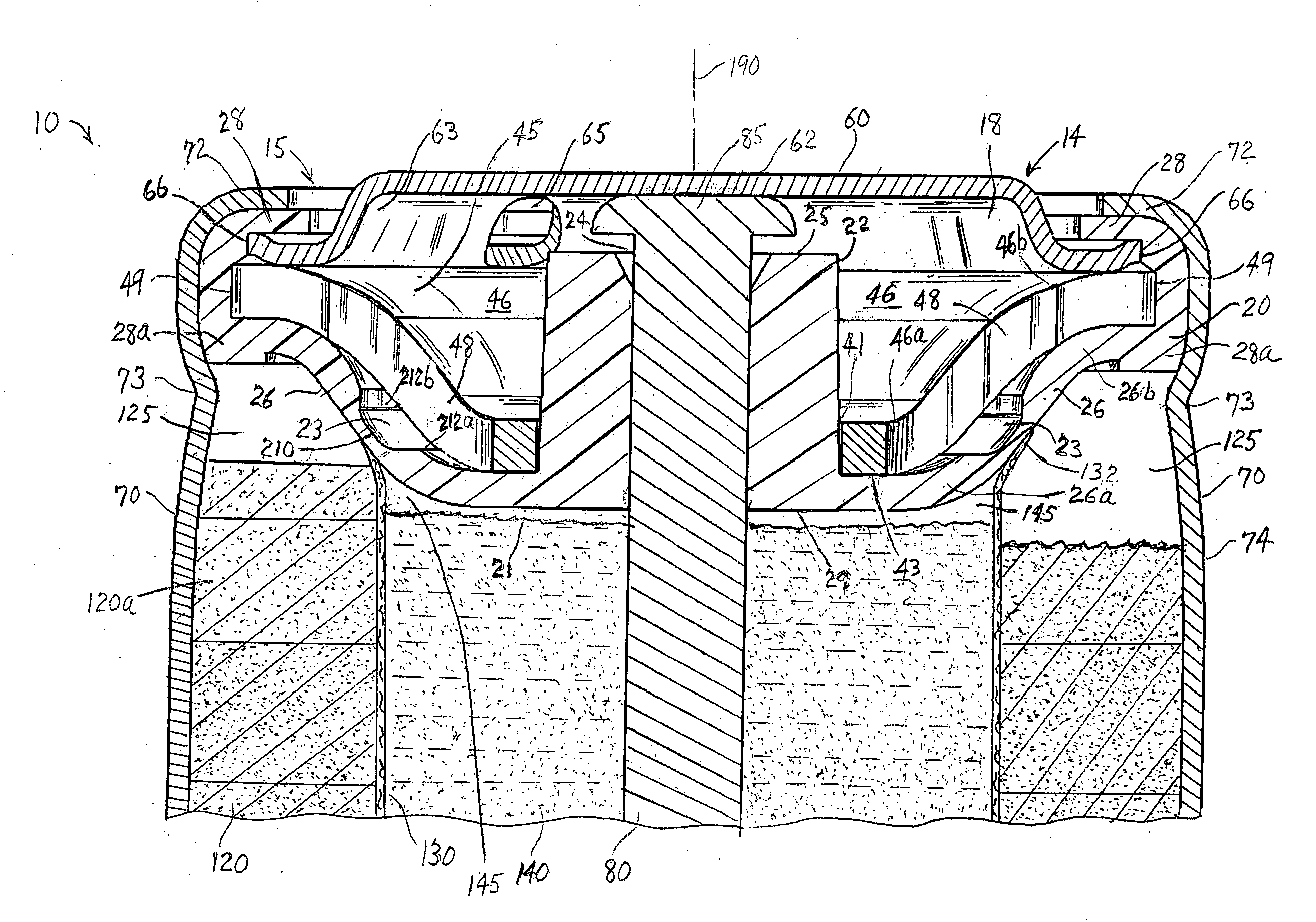
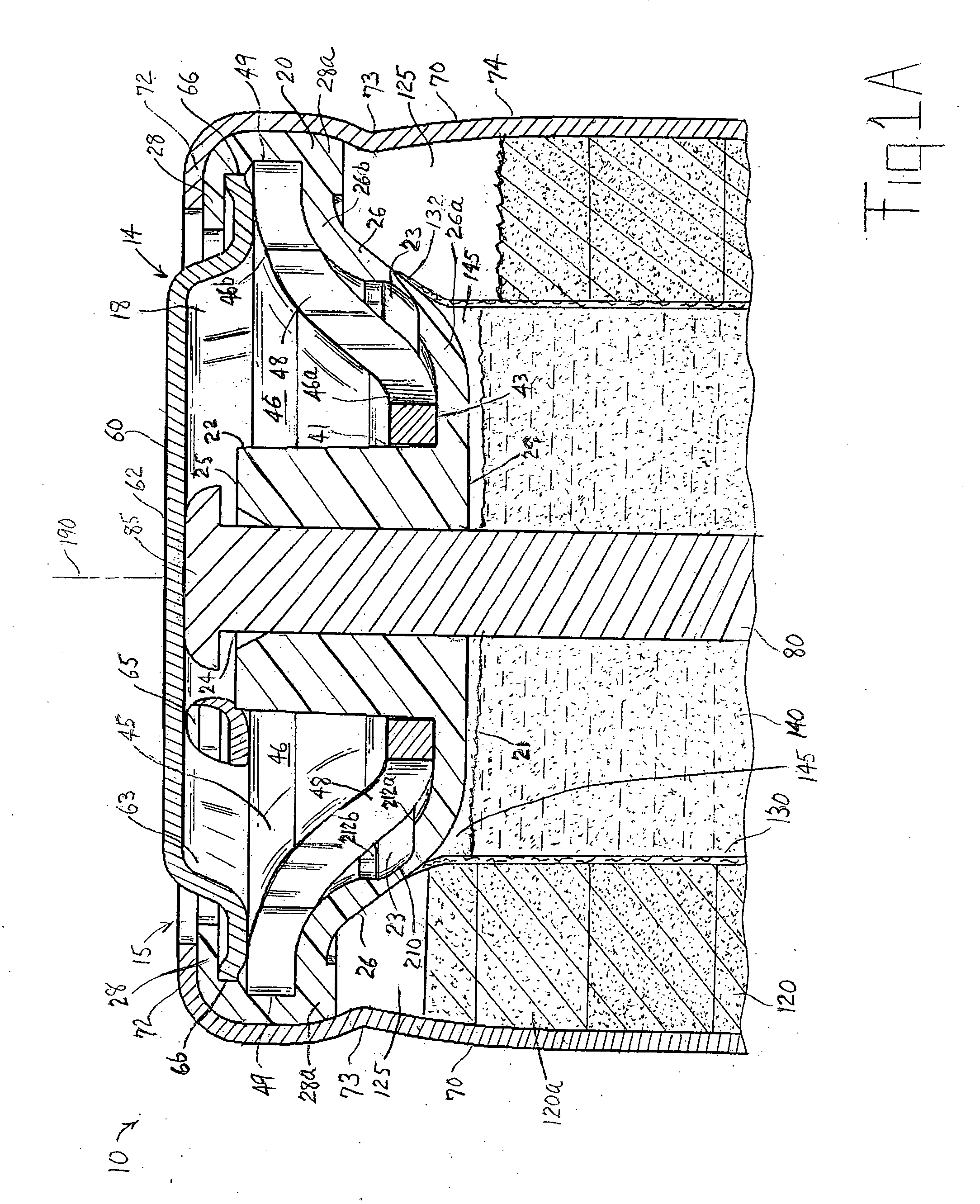
[0023]Because the radially extending walls of the metal support disk and underlying and abutting insulating disk form a concave or bowl shaped surface when the cell is viewed with the end cap assembly on top, there is more height available for cathode material. That is, the cathode column height available for cathode material is greater than in the design shown in prior art U.S. Pat. No. 6,887,614, for a given size cell. This is because the radially extending wall of the metal support disk and radially extending wall of the underlying insulating sealing disk are slanted upwardly instead of downwardly and the legs emanating from the base of the insulating sealing disk near the edge of the disk, for example legs as shown in U.S. Pat. No. 6,887,614; have been eliminated. Such configuration of the insulating disk of the present invention also eliminates the need for a circumferential skirt, for example, eliminates circumferential skirt 120 as shown in U.S. Pat. No. 6,991,872 B2, extending from the base of the insulating sealing disk and into the anode and cathode columns. These improvements in turn result in more available height for the cathode column so that cathode material can be loaded into the cell housing to a greater height for a given cell size.
[0024]Furthermore, the concave (inverted) shape of both the radially extending wall of the metal support disk and radially extending wall of underlying insulating sealing disk produces an anode column plug. Specifically, the concave shape of the radially extending wall of the insulating sealing disk plugs the top (open) end of the anode column directly, thus providing a more effective seal of the anode column. Also, the concave (inverted) configuration of said radially extending wall of the insulating sealing disk allows the top edge of the separator to be slanted outwardly along the underside of said radially extending wall of the insulating sealing disk and in the direction towards the peripheral edge of said disk. This provides a more effective partition between the anode and cathode columns, that is, resulting in less chance of anode material spilling into the cathode column during cell storage or discharge.
[0027]The groove on the inside surface of the upwardly extending wall insulating sealing disk forming the rupturable membrane portion is preferably made so that it circumvents the center of the insulating disk. At least the portion of such circumventing rupturable membrane abutting said aperture in the metal support disk ruptures when the cell pressure rises to a predetermined level. The rupturable membrane is preferably of nylon, polyethylene, or polypropylene. The end cap assembly of the invention allows the burst aperture to be made large because of the inclined orientation of the upwardly sloping arm of the metal support disk. The groove in the rupturable membrane allows for thinner membrane at the rupture point, that is, at the base of the groove. This in turn allows for a reduction in design rupture pressures and accompanying small cell housing wall thickness, e.g. between about 4 and 12 mil (0.10 and 0.30 mm), thereby increasing the amount of cell internal volume available for active anode and cathode material. For example, the end cap assembly of the invention may allow for a cell housing small wall thickness of between 4 and 8 mils (0.10 and 0.20 mm) for AA and AAA size cells and between about 10 and 12 mils (0.25 and 0.30 mm) for C and D size cells.
[0029]The end cap assembly of the invention has an elongated anode current collector which has a head that passes through the central aperture in the metal support disk so that it can be welded directly to the underside surface of the end cap. The head of the anode current collector is preferably welded directly to the underside of the end cap by electric resistance welding. There is no other welding of end cap assembly components required. Laser welding need not be employed anywhere in the cell assembly, thereby making the cell assembly process more efficient and less capital intensive.

Problems solved by technology

A problem associated with design of various electrochemical cells, particularly alkaline cells, is the tendency of the cell to produce gases as it continues to discharge beyond a certain point, normally near the point of complete exhaustion of the cell's useful capacity.
The end cap assembly disclosed in the reference is not designed to withstand radial compressive forces and will tend to leak when the cell is subjected to extremes in hot and cold climate.
Such legs, however, take up space within the cathode column within the cell interior, which could otherwise be used for additional cathode material.
Such design has the disadvantage of requiring an additional component, namely, the insulating washer which needs to be inserted into the end cap assembly.
In this respect use of the insulating washer does not make the cell tamper proof.
When the cell is subjected to intentionally abusive conditions such as exposure to fire, this may result in very quick rise in cell internal temperature and gassing.
Such design while adequately containing the top edge of the separator in order to partition the top of the anode column from the top of the cathode column, nevertheless results in unused space in these upper regions of the anode and cathode columns.
Lower design vent activation pressures, however, poses design challenges.
If an “island” type rupturable membrane is used to trigger the venting mechanism, there are practical limitations as to how thin such membrane can be molded using conventional molding techniques such as injection molding.
Also there are limitations on the amount of surface area available for such membranes depending on cell size.

Method used


Image

  • End cap seal assembly for an electrochemical cell
  • End cap seal assembly for an electrochemical cell
  • End cap seal assembly for an electrochemical cell

Examples


Embodiment Construction

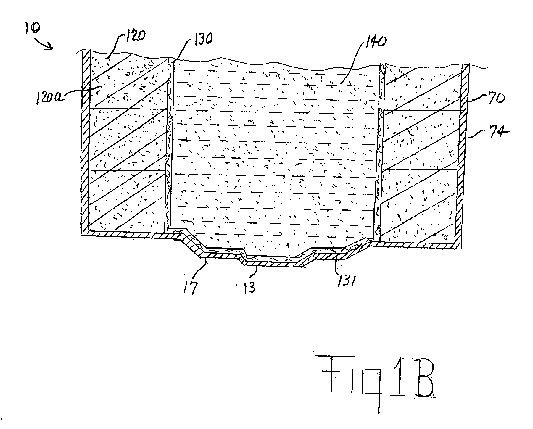
[0038]A preferred structure of the end cap assembly 14 of the invention within cell housing 70 is illustrated in FIG. 1A. The end cap assembly 14 of the invention has particular applicability to electrochemical cells comprising a cylindrical housing 70 (FIG. 2A) having an open end 15 and opposing closed end 17, wherein the end cap assembly 14 (FIG. 2B) is inserted into said open end 15, to seal the cell. The end cap assembly 14 is particularly applicable to cylindrical alkaline cells of standard AAA (44×10 mm), AA (50×14 mm), C (49×25.5 mm) and D (60×33 mm) size. The end cap assembly 14 is particularly useful for smaller size alkaline cells such as AAA and AA size cell, but may be used advantageously in the C and D size cells as well. Such alkaline cell, as cell 10 (FIGS. 1A and 1B), desirably has an anode 140 comprising zinc, a cathode 120 comprising MnO2, with electrolyte permeable separator 130 therebetween. The cathode may be in the form of stacked compacted disks 120a comprisin...


PUM

PropertyMeasurementUnit
angleaaaaaaaaaa
angleaaaaaaaaaa
angleaaaaaaaaaa

Abstract

An end cap seal assembly for an electrochemical cell such as an alkaline cell is disclosed. The end cap assembly comprises a metal support disk and underlying insulating sealing disk and a metal end cap overlying the metal support disk. The edge of the end cap and metal support disk is captured by the crimped edge of the insulating sealing disk. The support disk has an upwardly extending wall with at least one aperture therethrough. The insulating disk also has a slanted upwardly extending wall forming a rupturable membrane which underlies and abuts the inside surface of the upwardly extending wall of the support disk. The rupturable membrane underlies and abuts the aperture in the upwardly extending wall of the metal support disk. When gas pressure within the cell exceeds a predetermined level the rupturable membrane pushes through said aperture and ruptures allowing gas to escape therefrom to the environment.

Description

FIELD OF THE INVENTION[0001]The invention relates to an end cap assembly for sealing electrochemical cells, particularly alkaline cells. The invention relates to rupturable devices within the end cap assembly which allow gas to escape from the interior of the cell to the environment.BACKGROUND[0002]Conventional electrochemical cells, such as alkaline cells, are formed of a cylindrical housing having an open end and an end cap assembly inserted therein to seal the housing. Conventional alkaline cells typically comprise an anode comprising zinc, a cathode comprising manganese dioxide, and an alkaline electrolyte comprising aqueous potassium hydroxide. There is an electrolyte permeable separator sheet between anode and cathode. After the cell contents are supplied, the cell is closed by crimping the housing edge over the end cap assembly to provide a tight seal for the cell. The end cap assembly comprises an exposed end cap which functions as a cell terminal and typically a plastic ins...

Claims


Application Information

Patent Timeline
Patent Type & Authority Applications(United States)
IPC IPC(8): H01M2/12H01M2/02H01M50/119H01M50/167
CPCH01M2/0275H01M2/0285H01M6/08H01M2/1241H01M2/0413H01M50/171H01M50/3425H01M50/119H01M50/167
Inventor YOPPOLO, ROBERT A.
Owner THE GILLETTE CO
Learn More