
Regenerative process for removal of mercury and other heavy metals from gases containing H2 and/or CO

Active Publication Date: 2008-08-07
GAS TECH INST
View PDF4 Cites 33 Cited by
  • Summary
  • Abstract
  • Description
  • Claims
  • Application Information

AI Technical Summary

Benefits of technology

[0022]It also has been discovered that when the spent sorbent is exposed to a mercury-free and H2S / COS-free gas stream that contains H2 and / or CO, mercury is readily released from the sorbent at the same temperature as the capture process. To increase the rate of mercury release, it may be advantageous to increase the regeneration temperature by 5-100° C.
[0024]It has also been discovered that the mercury thus captured by the supported Cu sorbent is released easily when the spent sorbent is exposed at the same temperature (or slightly higher temperature) to a mercury-free gas stream containing a reducing gas, such as H2 and / or CO. Although not experimentally verified, it appears that during regeneration, H2 and / or CO breaks the Cu—S bond, thereby releasing Hg along with S as H2S.

Problems solved by technology

However, for IGCC systems, such low-temperature processes result in severe energy penalties and reduced efficiencies because the pressurized fuels / synthesis gases produced by the system have to be reheated to the operating temperature (greater than about 300° C.) of the gas turbines employed for electricity generation.
Development of a sorbent-based process for IGGC systems, however, is a major challenge and currently no proven technologies exist for the removal of trace levels of mercury from high-temperature fuels / synthesis gases.
Activated carbon-based sorbents remove mercury primarily by a physisorption mechanism, and they are not effective at higher temperatures.
In addition, exposure of impregnated sorbents to gaseous streams at high temperature (greater than about 120° C.) has been shown to release some of the active sulfur component in the gas stream, making the sorbent ineffective.
Another substantial issue is the presence of highly reactive hydrogen in the fuels / synthesis gases which can alter the chemical characteristics of an otherwise active sorbent, making it ineffective for mercury removal.
In addition, the reaction or interaction of mercury with the active component in the sorbent may not be favorable in the presence of hydrogen.
Under such conditions, CuS-based sorbents are not effective.
Thermodynamically, CuS is reduced in the presence of H2 and its reduced form, Cu2S, is ineffective for mercury capture.

Method used


Image

  • Regenerative process for removal of mercury and other heavy metals from gases containing H2 and/or CO
  • Regenerative process for removal of mercury and other heavy metals from gases containing H2 and/or CO
  • Regenerative process for removal of mercury and other heavy metals from gases containing H2 and/or CO

Examples


example 1

[0037]A sorbent containing 20 wt. % Cu on alumina was prepared using an incipient wetness method, which is well known to those skilled in the art. Copper nitrate was used as the source of copper. The support used was high surface area gamma-alumina having a surface area of about 255 m2 / g, a bimodal pore size distribution, a median pore size of about 70 microns and 5000 Å, and a total pore volume of about 1.14 cc / g. The support, in the form of ⅛-inch pellets was obtained from Alfa-Aesar. The prepared sorbent was dried at 100° C. for six (6) hours and calcined in air at 400° C. for an additional six (6) hours. The pellets were crushed and sieved to obtain particles in the range of about 250 microns to about 400 microns.

[0038]About 0.5 g of the sorbent was loaded into a quartz reactor enclosed in an electric furnace maintained at a temperature of about 150° C. Initially, the sorbent was pre-reduced in the presence of 2 vol % H2 in a N2 stream to obtain the reduced form of the sorbent. ...

example 2

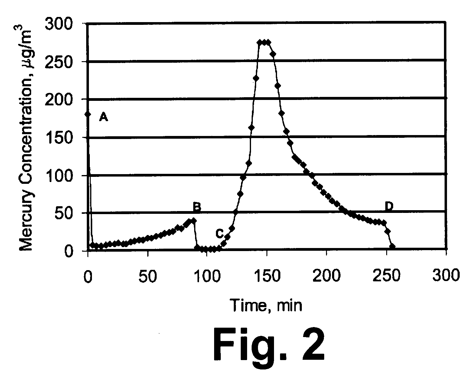
[0039]In order to show that the process of this invention is particularly suitable for supported / dispersed sorbent, an experiment was performed with a sorbent in which Cu was not deposited on a support. In this example, a pre-sulfided Cu-based sorbent (Katalco 83-3S) was obtained from Johnson Matthey Catalysts having an elemental composition of 8.56% by weight Al, 32.4% by weight Cu, 20% by weight Zn, and 14.3% by weight S. The sorbent had a surface area of 71 m2 / g and a porosity of 0.145 ml / g. About 1.5 g of the sorbent in the size range of about 180 to 250 microns was exposed to a gaseous stream containing 180 micro-g / m3 of mercury and 25% by volume H2, with the balance being N2, at 200° C. A breakthrough plot monitoring the outlet mercury concentration is shown in FIG. 3. Point A in FIG. 3 denotes the start of the exposure period. After about 110 minutes from the start of the exposure period, at Point B in FIG. 3, about 1250 ppm of H2S was added to the gaseous stream. FIG. 3 does...


PUM

PropertyMeasurementUnit
Temperatureaaaaaaaaaa

Abstract

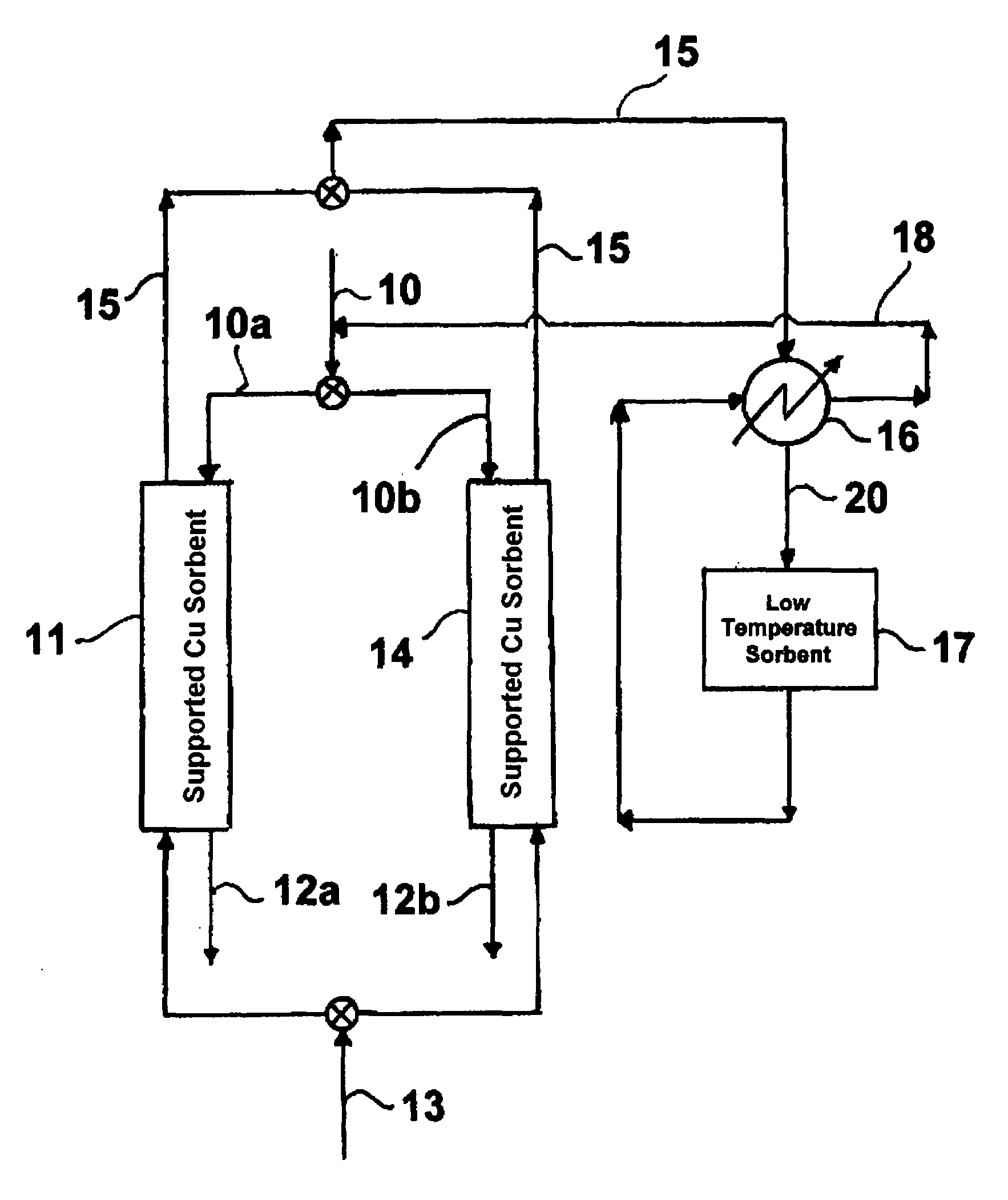
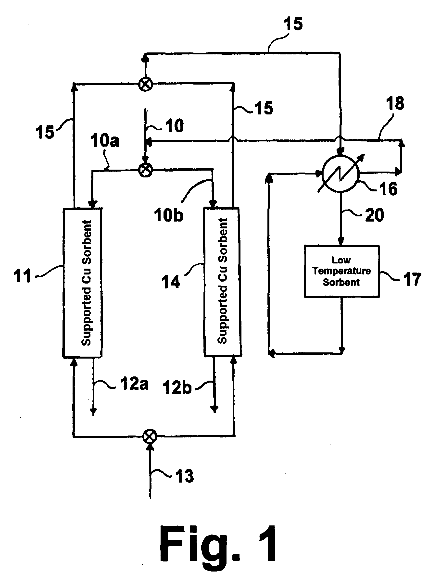
A method for removal of mercury from a gaseous stream containing the mercury, hydrogen and / or CO, and hydrogen sulfide and / or carbonyl sulfide in which a dispersed Cu-containing sorbent is contacted with the gaseous stream at a temperature in the range of about 25° C. to about 300° C. until the mercury concentration in the gaseous stream after contacting the sorbent exceeds a predetermined breakthrough level, signaling a spent sorbent. Arsenic, cadmium and selenium present in the gaseous stream may also be captured along with the mercury. The spent sorbent is then contacted with a desorbing gaseous stream at a temperature equal to or slightly higher than the temperature at which the mercury adsorption is carried out, producing a regenerated sorbent and an exhaust gas comprising released mercury. The released mercury in the exhaust gas is then captured using a high-capacity sorbent, such as sulfur-impregnated activated carbon, at a temperature less than about 100° C. The regenerated sorbent may then be used to capture additional mercury from the mercury-containing gaseous stream. The process may be carried out at pressures in the range of about 1 bar to about 200 bar.

Description

[0001]The U.S. Government has a paid-up license in this invention and the right in limited circumstances to require the patent owner to license others on reasonable terms as provided for by the terms of DOE Contract No. DE-FC26-04NT42312 awarded by the U.S. Department of Energy.BACKGROUND OF THE INVENTION[0002]1. Field of the Invention[0003]This invention relates to a method for removal of mercury from a reducing gas. More particularly, this invention relates to a regenerative method for removal of mercury from a reducing gas containing hydrogen and / or CO, such as a coal-gasifier fuel gas, at temperatures in the range of about 25° C. to about 300° C.[0004]2. Description of Related Art[0005]Because of the health effects of mercury on fish-eating populations, there is a growing concern of mercury emissions from man-made sources, especially from coal-burning power plants. Mercury regulations currently proposed by the U.S Environmental Protection Agency (EPA) for coal-fired power plants...

Claims


Application Information

Patent Timeline
IPC IPC(8): B01D53/02
CPCB01D53/02B01D53/10B01D2257/602B01D2253/112B01D2256/16B01D53/64
Inventor JADHAV, RAJA A.
Owner GAS TECH INST
Learn More