Solar Energy Collection Apparatus and Method

a solar energy and collection apparatus technology, applied in lighting and heating apparatus, instruments, machines/engines, etc., can solve the problems of poor process temperature control, less than optimal solar fireball focus, and catalyst sintering

Inactive Publication Date: 2008-08-07
SHEC LABS
View PDF19 Cites 25 Cited by
  • Summary
  • Abstract
  • Description
  • Claims
  • Application Information

AI Technical Summary

Problems solved by technology

In some solar thermo-chemical processing the image fireball is employed to directly heat catalyst beds in transparent process tubes often resulting in hotspots, causing catalyst sintering and poor process temperature control.
This results in a less than optimal focus of the solar fireball on the target and an increase in radiation losses due to the enlarged solar image size with the accompanying increased area of hot radiating surfaces.
Unfortunately as process temperatures increase, parasitic radiation loss follows Stefan's Law (Pr=σεAT4) such that losses due to thermal radiation increase sixteen fold for each doubling of the absolute temperature of the target, which is at the process temperature.

Method used


Image

  • Solar Energy Collection Apparatus and Method
  • Solar Energy Collection Apparatus and Method
  • Solar Energy Collection Apparatus and Method

Examples


Embodiment Construction

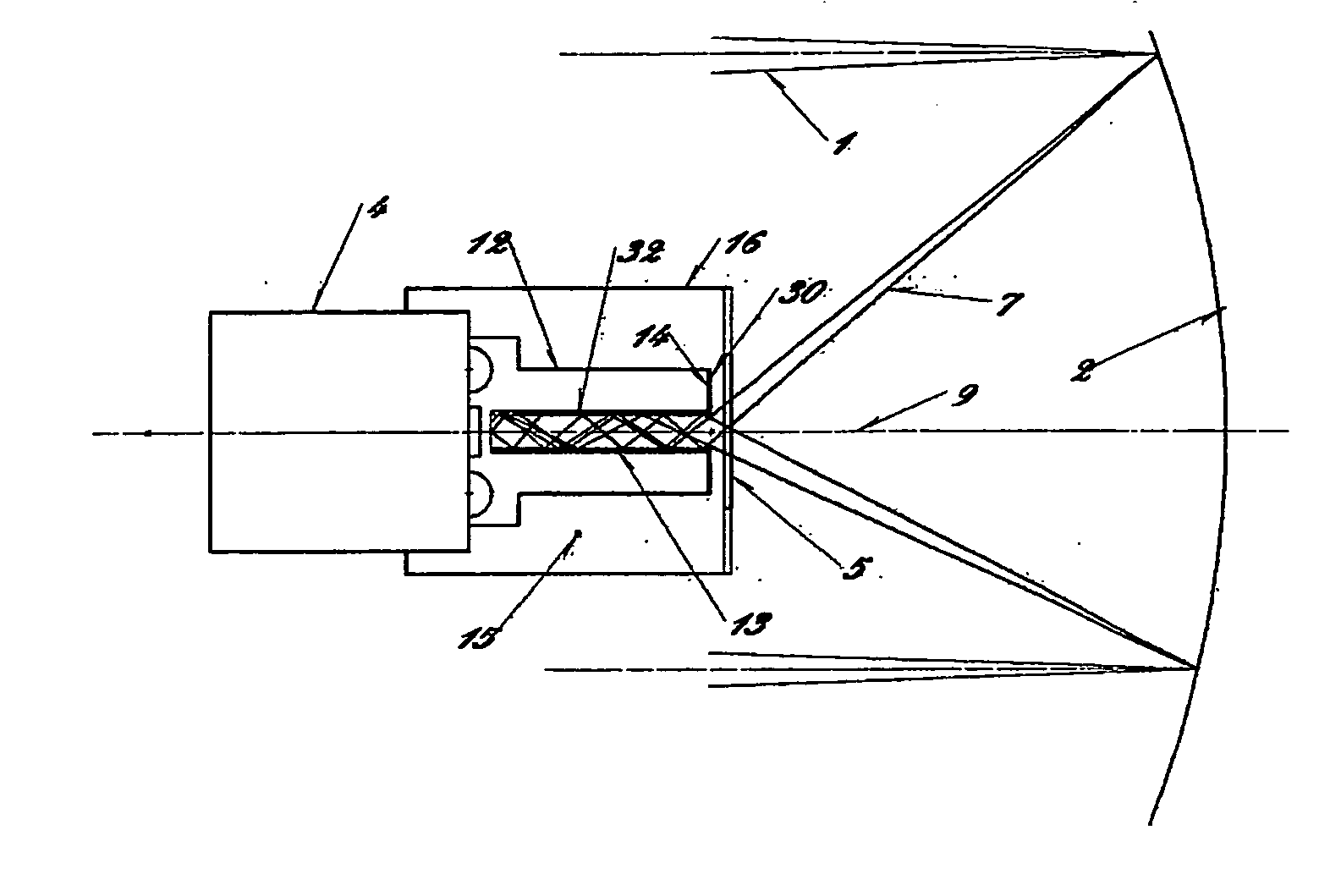
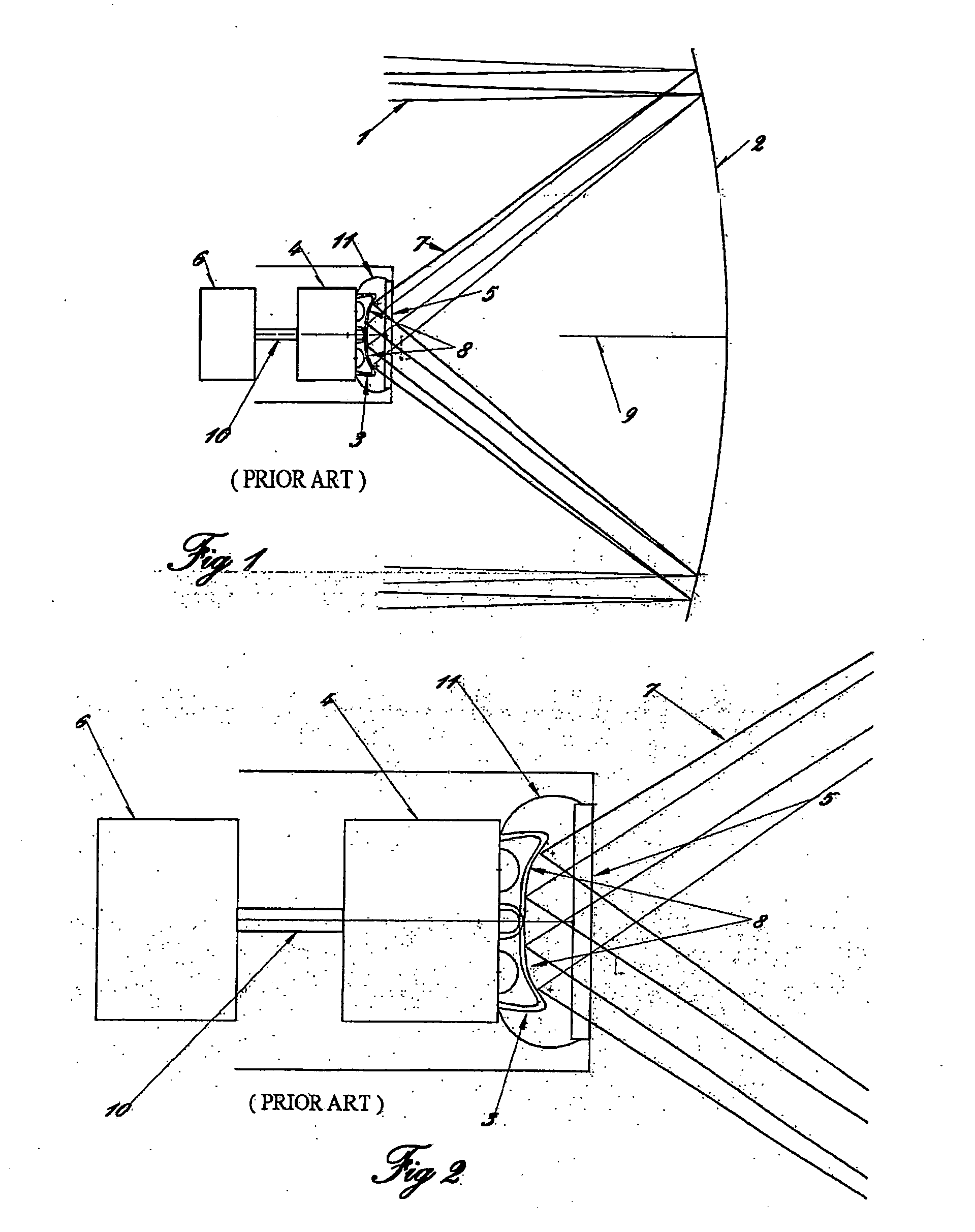
[0024]FIGS. 1 and 2 schematically illustrate a prior art system of solar heat collection driving a heat engine and electric generator combination. Solar heat collection systems are used to provide heat for a wide variety of purposes in which the collected heat is transferred to a heat sink, such as the illustrated heat engine, that essentially consumes the heat. The operating temperature will vary depending on the purpose, and the system will be designed such that all the collected heat will be drawn away by the heat sink once the operating temperature is at the desired temperature which can vary from about 100° C. to 1400° C. or more.

[0025]In this example solar radiation 1 is reflected by the solar concentrator 2 in solar rays 7 of a solar beam and focused on a target 8 positioned in a cavity 11 at the focus of a parabolic concentrator 2. The target 8 consists of a plurality of metal tubes 3 arranged symmetrically about the principal axis 9 of the parabolic solar concentrator 2 to ...


PUM


Abstract

An apparatus for collecting heat from a solar concentrator has an isothermal body defining an elongated cavity with a circular opening having a diameter equal to a diameter of a focus of the solar concentrator, the cavity having a reflective walls such that solar rays contacting the walls are substantially reflected. The circular opening is located at the focus of the solar concentrator and perpendicular to a principal axis of the solar concentrator, and the axis of the cavity is aligned with the principal axis of the solar concentrator. The heat generated in the isothermal body is absorbed by the heat sink. The length of the cavity is sufficient to absorb a desired proportion of the energy in the solar rays entering the cavity and is about 5 to 9 times the diameter of the opening of the cavity. Depending on material used, the isothermal body can be enclosed in a reducing atmosphere to maintain reflectivity of the cavity walls.

Description

[0001]This invention is in the solar energy field and in particular the collection of concentrated solar radiation for the purpose of driving a thermo-chemical, thermo-mechanical or other thermal process.BACKGROUND[0002]There exists today considerable interest in harnessing renewable solar thermal energy for a multitude of heat driven processes. These may include thermo-mechanical as in sterling engine or steam turbine power generation systems, thermo-chemical reforming, thermal-cracking, process heating, general heating, materials processing etc. Solar collection systems are usually placed in locations where sunlight is readily available. In a typical system mirrors either flat-segmented, or curved, are arranged in a parabolic or trough configuration to concentrate incident solar radiation on a predefined target. Tracking control systems or preprogrammed algorithms maintain the required optical geometry by moving the mirror as the sun transverses the sky.[0003]The target is usually...

Claims


Application Information

Patent Timeline
Patent Type & Authority Applications(United States)
IPC IPC(8): F24J2/10F24S20/20F24S23/70F24S23/71G02B7/198
CPCF03G6/06F24J2/07Y02E10/46Y02E10/41F24J2002/003F24S20/20F24S2023/88F24S23/70Y02E10/40
Inventor TUCHELT, MAURICE J.
Owner SHEC LABS
Why Eureka
Try Eureka