Bone treatment systems and methods

Inactive Publication Date: 2008-08-07
DFINE INC
View PDF101 Cites 101 Cited by
  • Summary
  • Abstract
  • Description
  • Claims
  • Application Information

AI Technical Summary

Benefits of technology

[0020]In an additional embodiment, a method for injecting a bone cement to treat an abnormality in a bone is provided. The method comprises providing a bone cement having a setting time of about 25 minutes or more, injecting the bone cement into a vertebra of a patient using a bone cement injector system, and applying energy to the bone cement from an energy emitter in the injector system to thereby increase the viscosity of the bone cement and accelerate the setting time of the bone cement.
[0021]In another embodiment, a method for anchoring an implant member in a bone with a bone cement is provided. The method comprises positioning an implant member in a bone of a patient. The method additionally comprises injecting a bone cement within the region of the bone-implant interface using an injector system. The bone cement has a setting time of about 25 min

Problems solved by technology

Medical advances aimed at slowing or arresting bone loss from aging have not provided solutions to this problem.
Osteoporosis affects the entire skeleton but most commonly causes fractures in the spine and hip.
Spinal or vertebral fractures also cause other serious side effects, with patients suffering from loss of height, deformity and persistent pain which can significantly impair mobility and quality of life.
Osteoporosis describes a condition of decreased bone mass that leads to fragile bones which are at an increased risk for fractures.
In an osteoporosis bone, the sponge-like cancellous bone has pores or voids that increase in dimension making the bone very fragile.
In an elderly patient, bone resorption can surpass bone formation thus resulting in deterioration of bone density.
Since the PMMA needs to be forced into the cancellous bone, the techniques require high pressures and fairly low viscosity cement.
Since the cortical bone of the targeted vertebra may have a recent fracture, there is the potential of PMMA leakage.
Leakage of PMMA during vertebroplasty can result in very serious complications including compression of adjacent structures that necessitate emergency decompressive surgery.
The exothermic reaction of PMMA carries potential catastrophic consequences if thermal damage were to extend to the dural sac, cord, and nerve roots.
Vertebroplasty patients

Method used


Image

  • Bone treatment systems and methods
  • Bone treatment systems and methods
  • Bone treatment systems and methods

Examples


Embodiment Construction

[0034]This application is related to the following U.S. patent and Provisional patent Applications: application Ser. No. 11 / 165,651 filed Jun. 24, 2005 titled Bone Treatment Systems and Methods; application Ser. No. 11 / 165,652 filed Jun. 24, 2005 titled Bone Treatment Systems and Methods; application Ser. No. 11 / 208,448 filed Aug. 20, 2005 titled Bone Treatment Systems and Methods; Application No. 60 / 713,521 filed Sep. 1, 2005 titled Bone Treatment Systems and Methods; and application Ser. No. 11 / 209,035 filed Aug. 22, 2005, titled Bone Treatment Systems and Methods. The entire contents of all of the above applications are hereby incorporated by reference and should be considered a part of this specification.

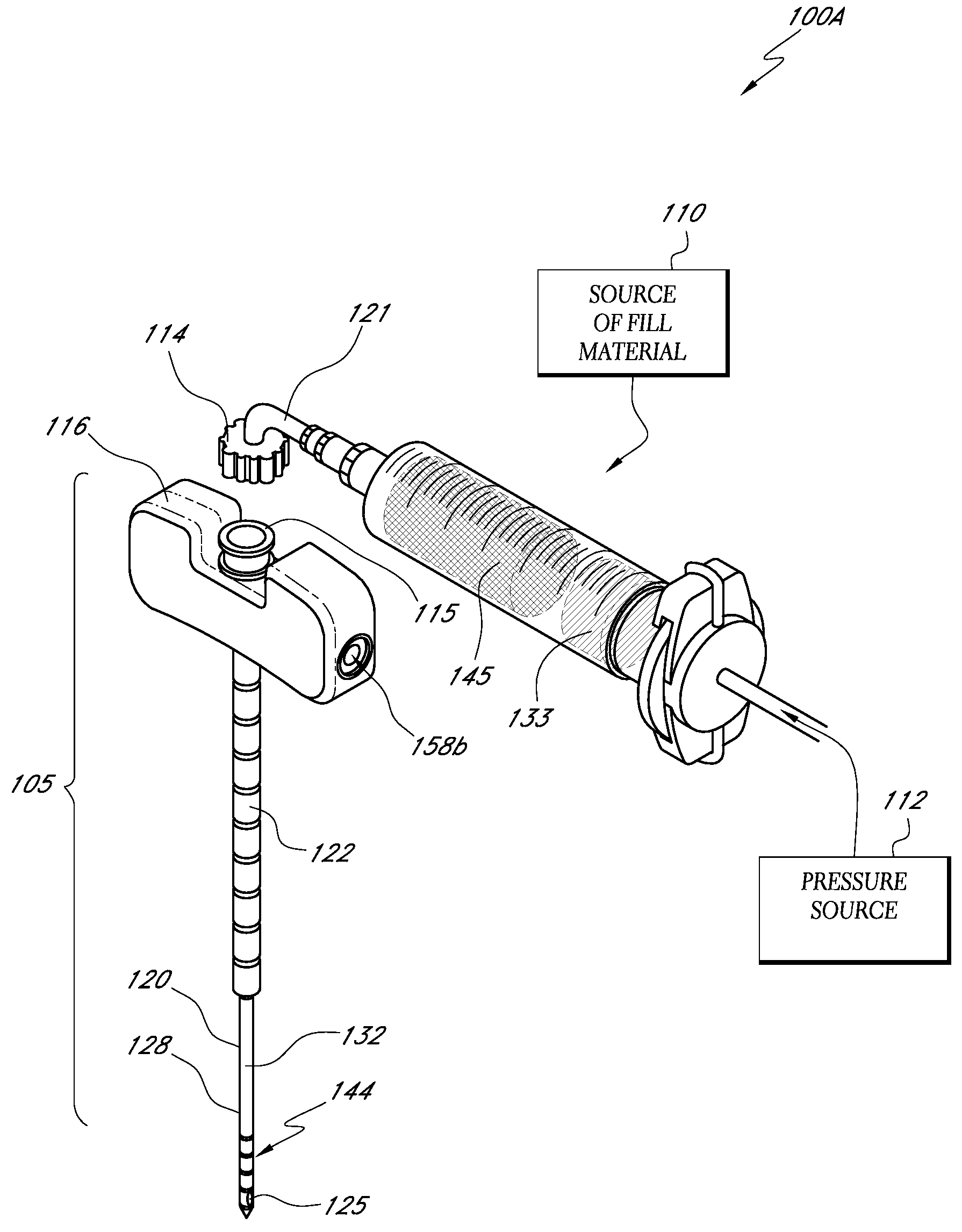
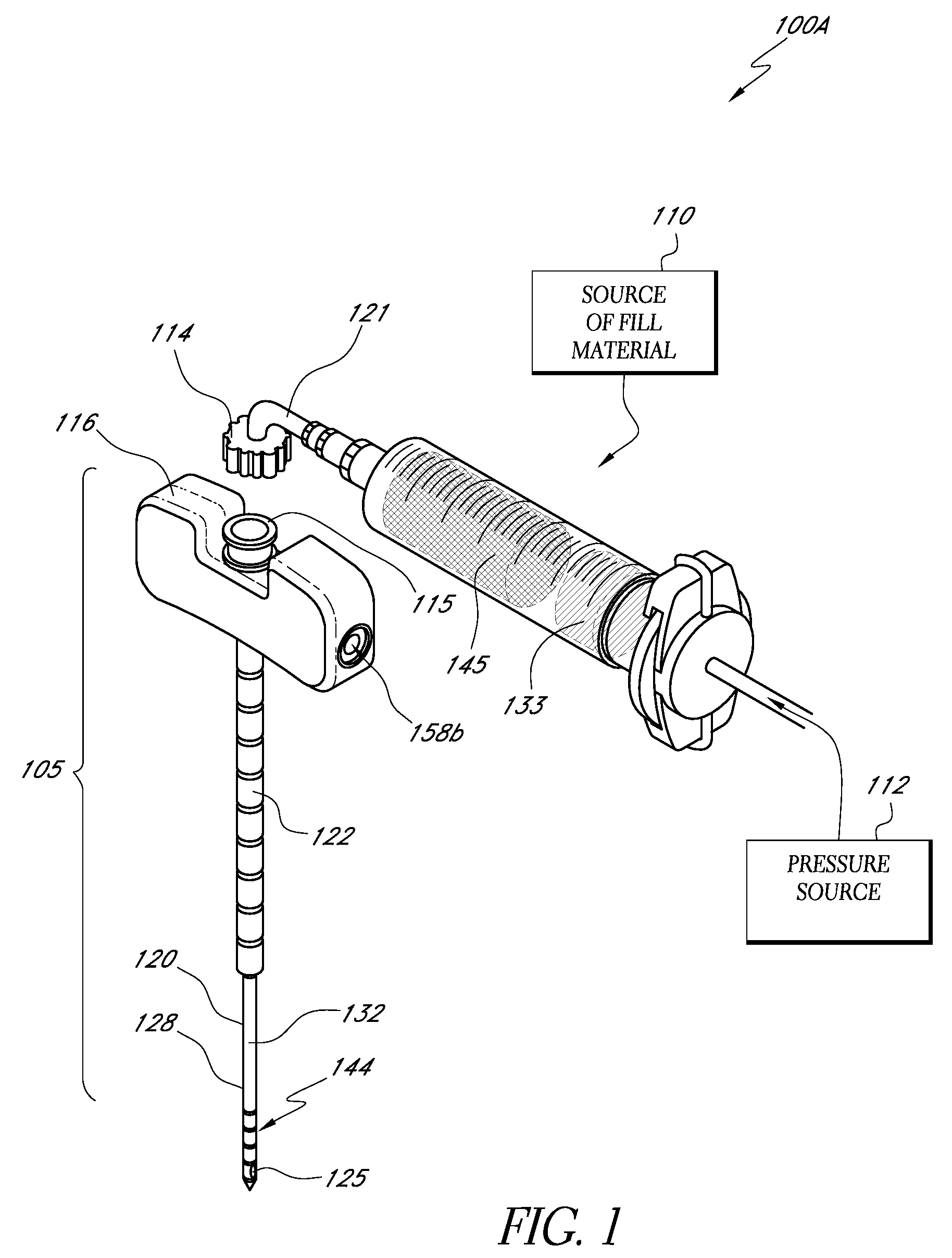
[0035]“Bone fill, fill material, or infill material or composition” includes its ordinary meaning and is defined as any material for infilling a bone that includes an in-situ hardenable material or that can be infused with a hardenable material. The fill material also can includ...


PUM

PropertyMeasurementUnit
Fractionaaaaaaaaaa
Fractionaaaaaaaaaa
Fractionaaaaaaaaaa

Abstract

Bone cement formulations are provided that have an extended working time for use in vertebroplasty procedures and other osteoplasty procedures. In one embodiment, a settable bone cement includes a polymerizable composition with a powder component comprising an X-Ray contrast medium and a liquid component, wherein the setting time of the cement is at least about 25 minutes, at least about 30 minutes, at least about 35 minutes, and at least about 40 minutes.

Description

CROSS-REFERENCE TO RELATED APPLICATIONS[0001]This application claims the benefit of priority under 35 U.S.C. §119(e) of U.S. Provisional Application No. 60 / 899,487, filed on Feb. 5, 2007, entitled Bone Treatment Systems and Methods.BACKGROUND OF THE INVENTION[0002]1. Field of the Invention[0003]Embodiments of the present invention relate to bone cement formulations that have an extended working time for use in vertebroplasty procedures and other osteoplasty procedures. Further embodiments of the present invention relate to bone cement formulations having extended working time together with cement injectors that include energy delivery systems for on-demand control of cement flow viscosity and flow parameters.[0004]2. Description of the Related Art[0005]Osteoporotic fractures are prevalent in the elderly, with an annual estimate of 1.5 million fractures in the United States alone. These include 750,000 vertebral compression fractures (VCFs) and 250,000 hip fractures. The annual cost ...

Claims


Application Information

Patent Timeline
IPC IPC(8): A61B17/58
CPCA61B17/8822A61B17/8836A61B2017/00026A61B2017/00088A61B2017/00101A61L24/0084A61L2430/02A61L24/06A61L27/16A61L27/46A61L27/50A61L24/02C08L33/12
Inventor LUZZI, ROBERTSHADDUCK, JOHN H.TRUCKAI, CSABA
Owner DFINE INC
Why Eureka
Try Eureka