Crankshaft lubrication system

a crankshaft and lubrication technology, applied in the direction of crankshaft lubrication, machines/engines, auxilaries, etc., can solve the problems of excessive supply rate of oil, and leakage of oil,

Inactive Publication Date: 2008-08-14
HONDA MOTOR CO LTD
View PDF12 Cites 17 Cited by
  • Summary
  • Abstract
  • Description
  • Claims
  • Application Information

AI Technical Summary

Benefits of technology

[0018]Thus the oil is supplied at a high oil supply rate to the heavily loaded end journals, and the oil is supplied at a low oil supply rate to the lightly loaded intermediate journals. Thus the oil can

Problems solved by technology

Therefore, the oil needs to be supplied at an excessively high supply rate to compensate the leakage to ensure proper lubrication of the crankpin.
Thus, such leakage has been an obstacle to the reduction of the capacity of the oil pump.
Then, the oil is supplied at an excessivel

Method used


Image

  • Crankshaft lubrication system
  • Crankshaft lubrication system
  • Crankshaft lubrication system

Examples


Embodiment Construction

[0032]Preferred embodiments of the present invention will be described with reference to FIGS. 1 to 10.

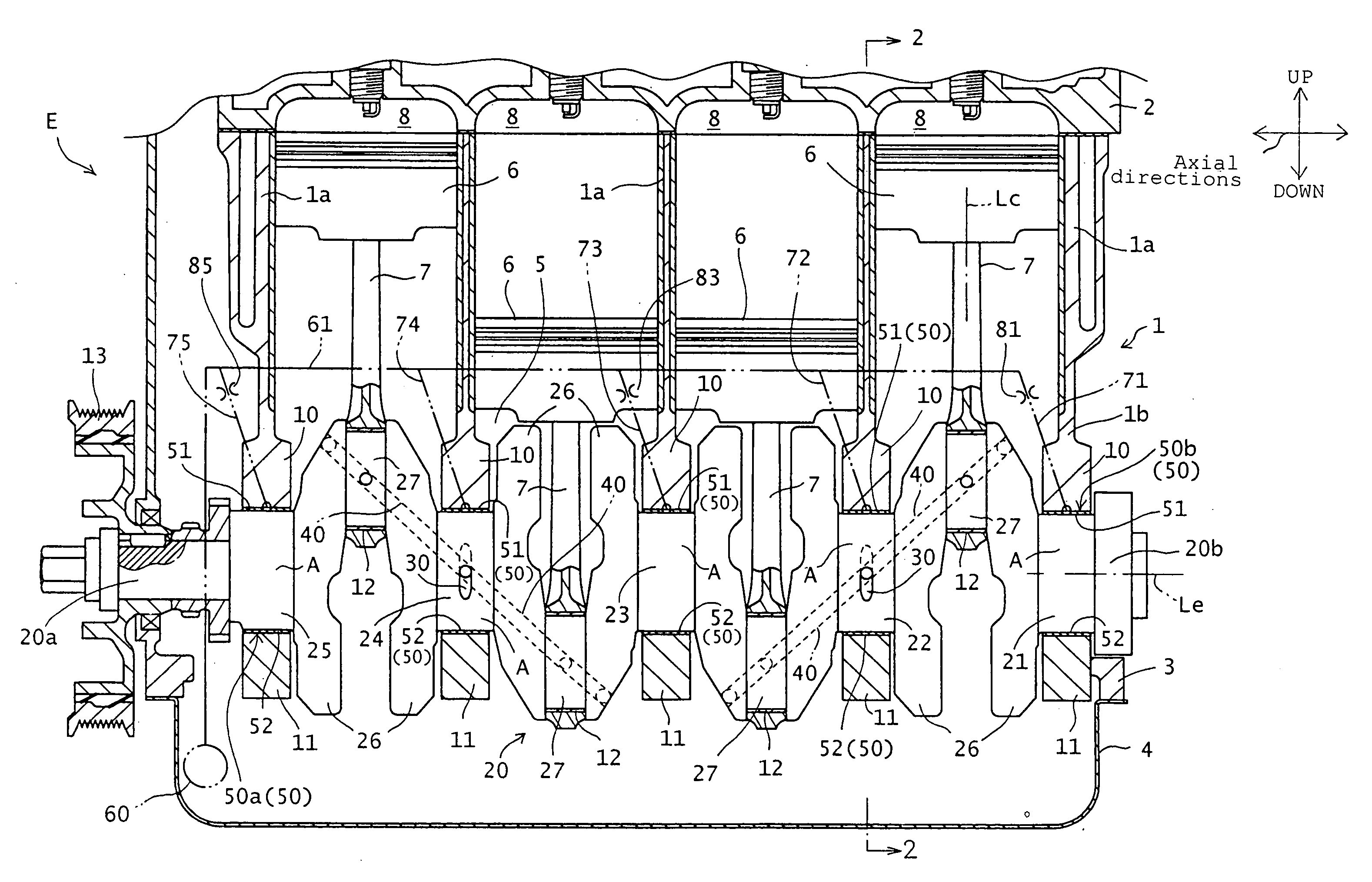
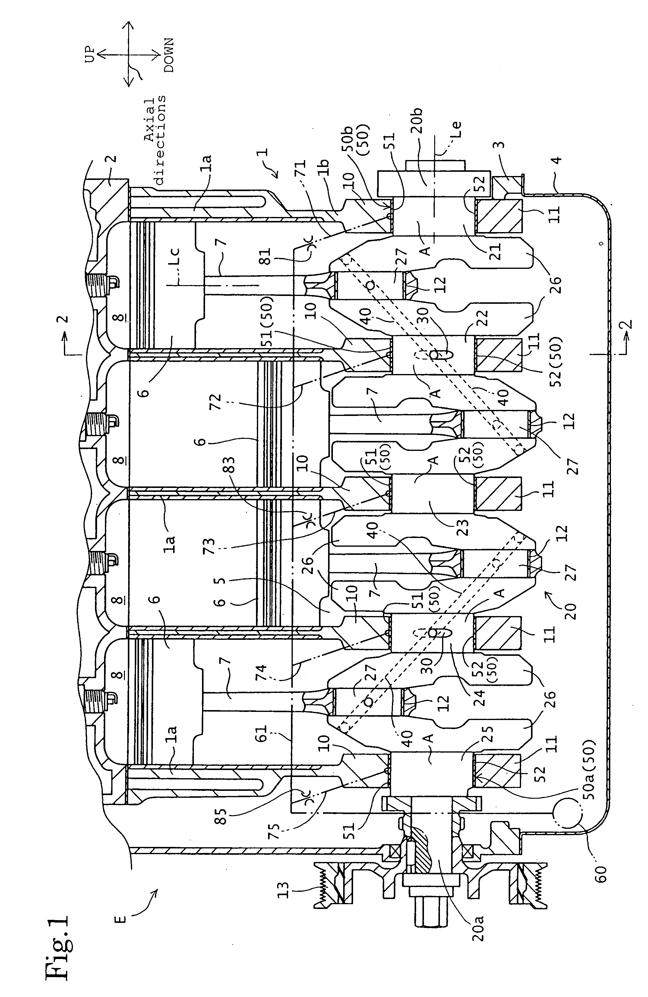
[0033]Referring to FIG. 1, a crankshaft lubrication system in a preferred embodiment of the present invention is incorporated into an automotive internal combustion engine E. The internal combustion engine E is an in-line 4-cylinder internal combustion engine. The engine E includes a cylinder block 1 provided with four cylinders 1a, a cylinder head 2 joined to an upper part of the cylinder block 1, a lower block 3 joined to a lower part 1b of the cylinder block 1, and an oil pan 4 joined to the lower surface of the lower part 1b of the cylinder block 1. The lower part 1b of the cylinder block 1, the lower block 3 and the oil pan 4 form a crankcase defining a crank chamber 5. A crankshaft 20 is supported for rotation in the crank chamber 5.

[0034]In this specification, the terms “axial direction”, “diametrical direction” and “circumferential direction” signify a direction parallel to...


PUM


Abstract

A crankshaft of an internal combustion engine has journals provided with shaft oil passages for carrying the oil to crankpins, and guide grooves having parts in which the shaft oil passages open, respectively, and opening in the cylindrical surfaces of the journals, respectively. The guide grooves has downstream end parts into which the shaft oil passages open, respectively, and extend in a circumferential direction in which the crankshaft rotates from the downstream end parts, respectively. First half bearing members of bearings are provided in their bearing surfaces with oil grooves through which the oil is supplied to the guide grooves, respectively. Each of the oil grooves are diametrically opposite to each of the guide grooves. The oil grooves have an axial width (W5) smaller than the axial width (W3) of the guide grooves. Thus oil leakage from gaps between each of the bearings and each of the journals of the crankshaft is reduced and hence an oil pump having a small capacity can be used.

Description

BACKGROUND OF THE INVENTION[0001]1. Field of the Invention[0002]The present invention relates to a crankshaft lubrication system including bearings provided with oil grooves, and a crankshaft having journals supported by and turns in the bearings and lubricated with lubricant or oil supplied through the oil grooves. The crankshaft lubrication system is incorporated into, for example, an internal combustion engine.[0003]2. Description of the Related Art[0004]A crankshaft lubrication system disclosed in, for example, JP-U 6-43202 includes bearings lubricated with lubricant or oil pumped out by an oil pump, and a crankshaft having journals supported by and turn in the bearings. Each of the journals is provided with a shaft oil passage through which the oil flows to a crankpin, and a guide groove into which the oil passage opens.[0005]The guide groove extending in the rotating direction of the crankshaft increases the pressure of the oil flowing toward the crankpin, which enables the oi...

Claims


Application Information

Patent Timeline
IPC IPC(8): F01M1/06
CPCF01M2001/062F01M1/06F16C3/14F16C2360/22
Inventor OHTA, NOBUYUKI
Owner HONDA MOTOR CO LTD
Why Eureka
Try Eureka