Composite Material, Light Emitting Element and Light Emitting Device

a technology of light emitting element and composite material, which is applied in the field of composite material, can solve the problems of poor transmittance, reduced power consumption, and many challenges, and achieve excellent carrier injecting property, excellent carrier transporting property, and excellent transparency

Active Publication Date: 2008-08-14
SEMICON ENERGY LAB CO LTD
View PDF62 Cites 26 Cited by
  • Summary
  • Abstract
  • Description
  • Claims
  • Application Information

AI Technical Summary

Benefits of technology

[0016]By implementing the present invention, a composite material of an organic compound and an inorganic compound, and has an excellent carrier transporting property, an excellent carrier injecting property to the organic compound, as well as excellent transparency, can be provided.
[0017]Also, by applying the composite material to a current excitation light emitting element, a light emitting element that is excellent in both driving volt...

Problems solved by technology

In this manner, there are hopes for the current excitation light emitting element using an organic compound material having a light emitting property to be applied to light emitting devices and illuminations; however, many challenges still remain.
Reduction in power consumption is one of those challenges.
However, as described in the Non-Patent Document 1, PAni has a problem that transmittance becomes poor when a film thickness becomes thick.
In other words, since the problem is with the transparency of the material itself that is used for the buff...

Method used


Image

  • Composite Material, Light Emitting Element and Light Emitting Device
  • Composite Material, Light Emitting Element and Light Emitting Device
  • Composite Material, Light Emitting Element and Light Emitting Device

Examples


embodiment mode 1

[0044]A structure of the composite material of the present invention will be described. The composite material of the present invention is a composite material of an organic compound having a particular skeleton and an inorganic compound. There is no limitation for a manufacturing method of the composite material of the present invention; however, it can be formed by a co-evaporation method where the organic compound and the inorganic compound are deposited simultaneously. The mixing ratio, in molar ratio, of the organic compound and the inorganic compound of the present invention is preferably around 1:0.1 to 1:10, and more desirably, 1:0.5 to 1:2. When forming the composite material by a co-evaporation method, the mixing ratio can be controlled by adjusting the deposition rate for each of the organic compound and the inorganic compound.

[0045]Organic compounds that can be used for the composite material of the present invention are the organic compound which are represented by the ...

embodiment mode 2

[0062]A light emitting element of the present invention will be described. The light emitting element of the present invention includes a layer containing a light emitting substance and a layer formed of a composite material between a pair of electrodes. Note that the composite material is the composite material of the present invention described in Embodiment Mode 1.

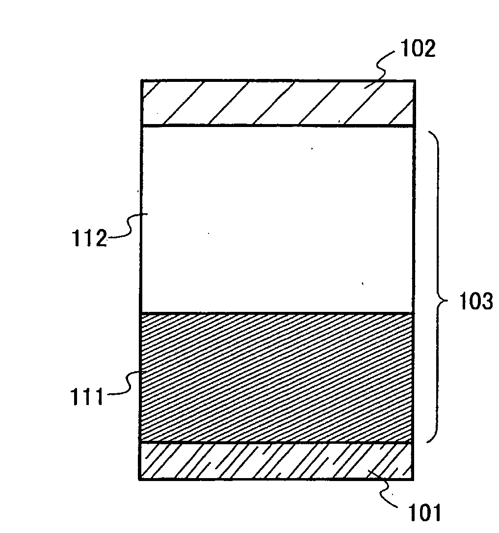
[0063]One example of a structure of the light emitting element of the present invention is shown in FIG. 1. The structure is that of interposing a light emitting laminated body 103 between a first electrode 101 and a second electrode 102. In this embodiment mode, a case where the first electrode 101 is an electrode functioning as an anode and the second electrode 102 is an electrode functioning as a cathode is described. For the first electrode 101 and the second electrode 102, a metal, an alloy, or an electroconductive compound can be used. For example, a metal having a conductive property such as aluminum (Al), silver...

embodiment mode 3

[0084]In this embodiment mode, a manufacturing method of the light emitting element shown in Embodiment Mode 2 will be described.

[0085]First, the first electrode 101 is formed. The first electrode 101 may be appropriately formed using a material such as those mentioned in Embodiment Mode 2, by a known method such as a sputtering method or an evaporation method.

[0086]Next, the first layer 111 is formed. A formation method of the first layer 111 is not particularly limited; however, it can be formed by co-evaporation of an organic compound and an inorganic compound which can be used for the composite material described in Embodiment Mode 1.

[0087]Then, the second layer 112 is formed. The second layer 112 can be formed by a known method and by using a known material; however formation by an evaporation method is common.

[0088]The second electrode 102 can be formed by a known method and by using a known material. Specifically, the materials listed in Embodiment Mode 2 as the materials for...


PUM

PropertyMeasurementUnit
Lightaaaaaaaaaa

Abstract

An object of the present invention is to provide a composite material formed of an organic compound and an inorganic compound, and has an excellent carrier transporting property, an excellent carrier injecting property to the organic compound, as well as excellent transparency. A composite material of the present invention for achieving the above object is a composite material of an organic compound represented in the general formula below, and an inorganic compound. For the inorganic compound, an oxide of a transition metal, preferably an oxide of a metal belonging to groups 4 to 8 of the periodic table, in particular vanadium oxide, tantalum oxide, molybdenum oxide, tungsten oxide, rhenium oxide, and ruthenium oxide, can be used.

Description

TECHNICAL FIELD[0001]The present invention relates to a composite material having an organic compound and an inorganic compound. Also, the present invention relates to a current excitation light emitting element using the composite material.BACKGROUND ART[0002]In recent years, research and development for light emitting elements using organic compounds having light emitting properties, have been actively pursued. A basic structure for these light emitting elements is that of interposing a layer including an organic compound having a light emitting property between a pair of electrodes. By applying voltage to such an element, electrons and holes are injected from the pair of electrodes into the layer including an organic compound having a light emitting property, and current flows. Then, by those carriers (electrons and holes) recombining, the organic compound having a light emitting property forms an excited state, and light is emitted when the excited state returns to a ground stat...

Claims


Application Information

Patent Timeline
IPC IPC(8): H01J63/04C07D209/56
CPCH01L51/0032H01L51/0052H01L51/0058H01L51/0072H01L51/5088H01L2251/303H01L51/5004Y10S428/917H01L51/5068H01L51/0051H01L51/5278H10K85/00H10K85/626H10K85/615H10K85/6572H10K50/17H10K50/19H10K50/11H10K50/157H10K85/611H10K2101/40H10K2102/00
Inventor IWAKI, YUJISEO, SATOSHIKUMAKI, DAISUKE
Owner SEMICON ENERGY LAB CO LTD
Why Eureka
Try Eureka