Eureka AIR delivers breakthrough ideas for toughest innovation challenges, trusted by R&D personnel around the world.

Test Point Insertion and Scan Chain Reordering for Broadcast-Scan Based Compression

Inactive Publication Date: 2008-08-14
NEC LAB AMERICA
View PDF8 Cites 13 Cited by
  • Summary
  • Abstract
  • Description
  • Claims
  • Application Information

AI Technical Summary

Benefits of technology

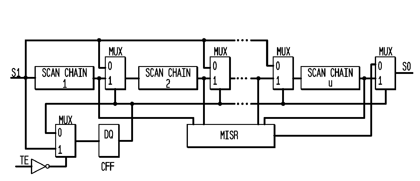
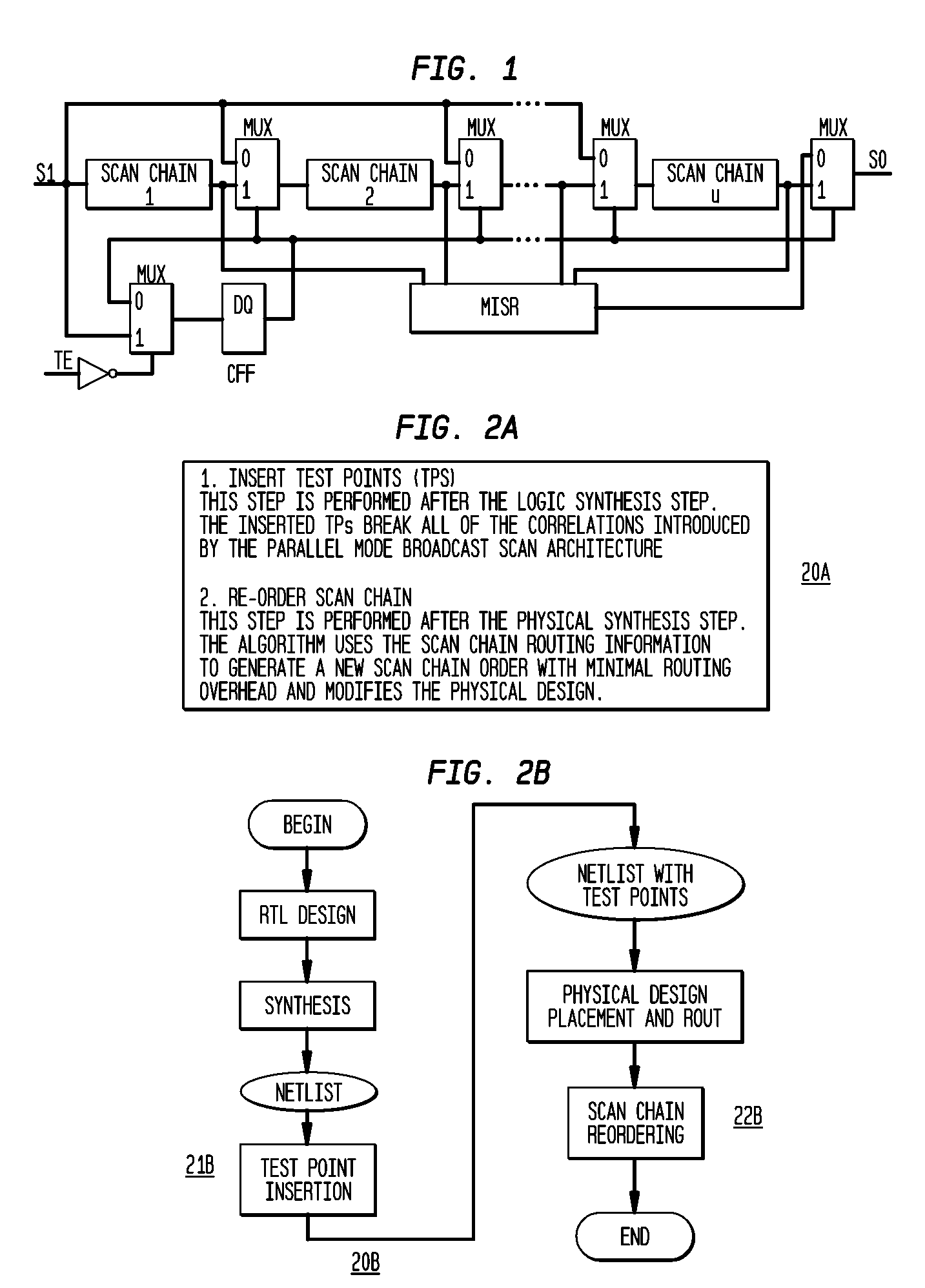
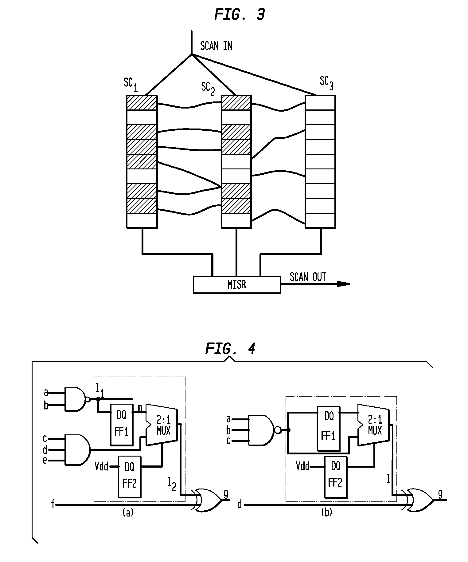
[0007]In accordance with the invention, a method for increasing fault coverage and compression with a broadcast scan-based test data compression circuit includes inserting test points for breaking correlations existing between scan inputs that belong to same scan slices making some faults un-testable with a broadcast scan-based test data compression circuit; and reordering scan inputs for further reducing correlations between scan inputs that belong to the same scan slices. In the preferred embodiment, inserting the test points includes identifying scan groups that are defined as sets of scan chains that are driven by same scan chain inputs, and inserting the test points includes determining gain functions for all signal lines in the circuit for choosing places to insert the test points, the gain function reflecting the number

Problems solved by technology

Due to ever increasing design size, the cost for testing large application specific integrated circuit (ASIC) designs have sky rocketed.
Shrinking process parameters have further aggravated the testing problem because new types of defects such as crosstalk noise, small delay defects, etc., are manifested in the device.
Now test engineers require new defect oriented fault models to detect these defects, which is fueling the test cost.
Since test application time directly affects the overall turn-around time of the design, it increases the unit cost of the chip.
Since ATEs have limited memory, channel capacity, and bandwidth, large test volume can affect the overall test time, adding to the test cost.
Several BIST schemes have been proposed, but are not widely used in the industry because of their inability to achieve the desired test quality.
Hence, for the designs with large number of scan flip-flops (SFFs), the LFSR hardware overhead becomes prohibitively expensive.
A disadvantage of the compression technique is that additional hardware is required to decode the test pattern.
However, it introduces several undesired correlations among different signal lines in the circuit that severely affect the performance of both the test generation and the test compaction tools.

Method used


Image

  • Test Point Insertion and Scan Chain Reordering for Broadcast-Scan Based Compression
  • Test Point Insertion and Scan Chain Reordering for Broadcast-Scan Based Compression
  • Test Point Insertion and Scan Chain Reordering for Broadcast-Scan Based Compression

Examples


Embodiment Construction

[0022]The invention includes a test-point-insertion TPI technique that can break broadcast scan architecture correlations among different signal lines in the circuit that severely affect the performance of both the test generation and the test compaction tools to make the design more amenable for test generation and test compaction. The invention includes a scan chain re-ordering technique that further reduces the correlations, which drastically reduces the test data volume and the test application tine. It uses the layout information and restricts the distance by which a particular scan flip-flop can be moved in the layout to minimize the scan chain routing overhead due to the proposed re-ordering operation. This also makes it more practical as any post-synthesis layout modification can be easily accommodated. The inventive TPI and scan chain re-ordering enables a design for-test scheme that can be integrated into any existing very large scale integrated VLSI design flow without im...


PUM


Abstract

A method for increasing fault coverage and compression with a broadcast scan-based test data compression circuit includes inserting test points for breaking correlations existing between scan inputs that belong to same scan slices making some faults un-testable with a broadcast scan-based test data compression circuit; and reordering scan inputs for further reducing correlations between scan inputs that belong to the same scan slices.

Description

[0001]This application claims the benefit of U.S. Provisional Application No. 60 / 888,813, entitled “Design-for-Test Technique to Enhance Performance of Broadcast Scan-Based Compressor”, filed on Feb. 8, 2007, the contents of which is incorporated by reference herein.BACKGROUND OF THE INVENTION[0002]The present invention relates generally to compression testing of large application specific integrated circuits, and more particularly, to enhancing performance of broadcast-scan based test compression by test point insertion and scan chain reordering techniques.[0003]Due to ever increasing design size, the cost for testing large application specific integrated circuit (ASIC) designs have sky rocketed. Shrinking process parameters have further aggravated the testing problem because new types of defects such as crosstalk noise, small delay defects, etc., are manifested in the device. Now test engineers require new defect oriented fault models to detect these defects, which is fueling the ...

Claims


Application Information

Patent Timeline
IPC IPC(8): G01R31/3181G06F11/26
CPCG01R31/318547
Inventor WANG, SEONGMOON
Owner NEC LAB AMERICA
Why Eureka
Eureka Blog
Learn More