Dispersing or milling apparatus, and dispersing or milling method using same

a technology of dispersing or milling and dispersing or milling method, which is applied in the direction of gas current separation, application, grain treatment, etc., can solve the problems of violent collapse of small vacuum bubbles, and achieve the effects of large cavitation, strong shearing force, and acceleration of movemen

Active Publication Date: 2008-08-21
NAT INST FOR MATERIALS SCI +1
View PDF8 Cites 15 Cited by
  • Summary
  • Abstract
  • Description
  • Claims
  • Application Information

AI Technical Summary

Benefits of technology

[0011]Another object of the present invention is to provide an apparatus and method for dispersing and milling a material containing a liquid and solid particles to obtain finely milled particles of nanometer size and that can be economically used on a commercial scale and that overcome the aforementioned problems of known apparatuses and methods.
[0012]A further object of the present invention is to provide an apparatus and method for dispersing and milling a material containing a liquid and solid particles to obtain finely milled particles of nanometer size and which utilize shock waves generated by ultrasonic waves to accelerate movement of milling media to improve dispersion and milling efficiency.
[0017]In the present invention, the shock waves generated by irradiation of the material with ultrasonic waves causes the aggregated nano particles to vigorously collide with one another and also causes the nano particles to vigorously collide against the milling media. This is particularly effective when the concentration of particles is low. At the same time, the milling media also receive the shock waves, which accelerates movement of the milling media. Since the milling media are vigorously stirred in the vessel, the milling media are thoroughly and energetically moved and strong shearing forces are generated by collision of the milling media with one another. The shearing forces generated by collision of the milling media, collision of the nano particles with one another and collision of the nano particles against the milling media act in corporation with one another to extremely finely mill the solid particles so as to obtain desired nano particles. The milling and dispersing apparatus can be used effectively at practical production levels.
[0018]Further, since the average particle size of nano particles thus obtained is at most about 100 nm, it is possible to separate the milling media therefrom by making the particle size of the milling media at least 15 μm, and the milling media can be accelerated and vigorously moved by shock waves generated by the ultrasonic waves by making the particle size of the milling media at most 1.0 mm. When the ultrasonic generator is disposed inside the vessel of the bead mill, the particle size of the milling media is preferably within a range of 0.5 mm to 1.0 mm by which classification of nano particles and beads can more assuredly be made and sufficient movement of the milling media by the shock waves can be made when the apparatus is used at practical production levels. When the ultrasonic generator is disposed in a tank functioning as both a supply tank and a recovery tank in the bead mill, there is no problem in practical production so far as the particle size of the milling media is any size within a range of 15 μm to 1.0 mm.
[0019]Further, when the frequency of ultrasonic waves is 15 KHz to 30 KHz and the amplitude is 5 μm to 50 μm, large cavitation can be securely generated, the shock waves produced upon decay of the cavitation become strong, and aggregated nano particles and milling media can be vigorously and thoroughly moved, so as to conduct sufficient dispersion and milling. More preferably, the frequency of ultrasonic wave is 15 KHz to 20 KHz and the amplitude is 20 μm to 50 μm.

Problems solved by technology

The ultrasonic waves generate alternating low-pressure and high-pressure waves in the liquid, resulting in the formation and violent collapse of small vacuum bubbles.

Method used


Image

  • Dispersing or milling apparatus, and dispersing or milling method using same
  • Dispersing or milling apparatus, and dispersing or milling method using same
  • Dispersing or milling apparatus, and dispersing or milling method using same

Examples


example 1

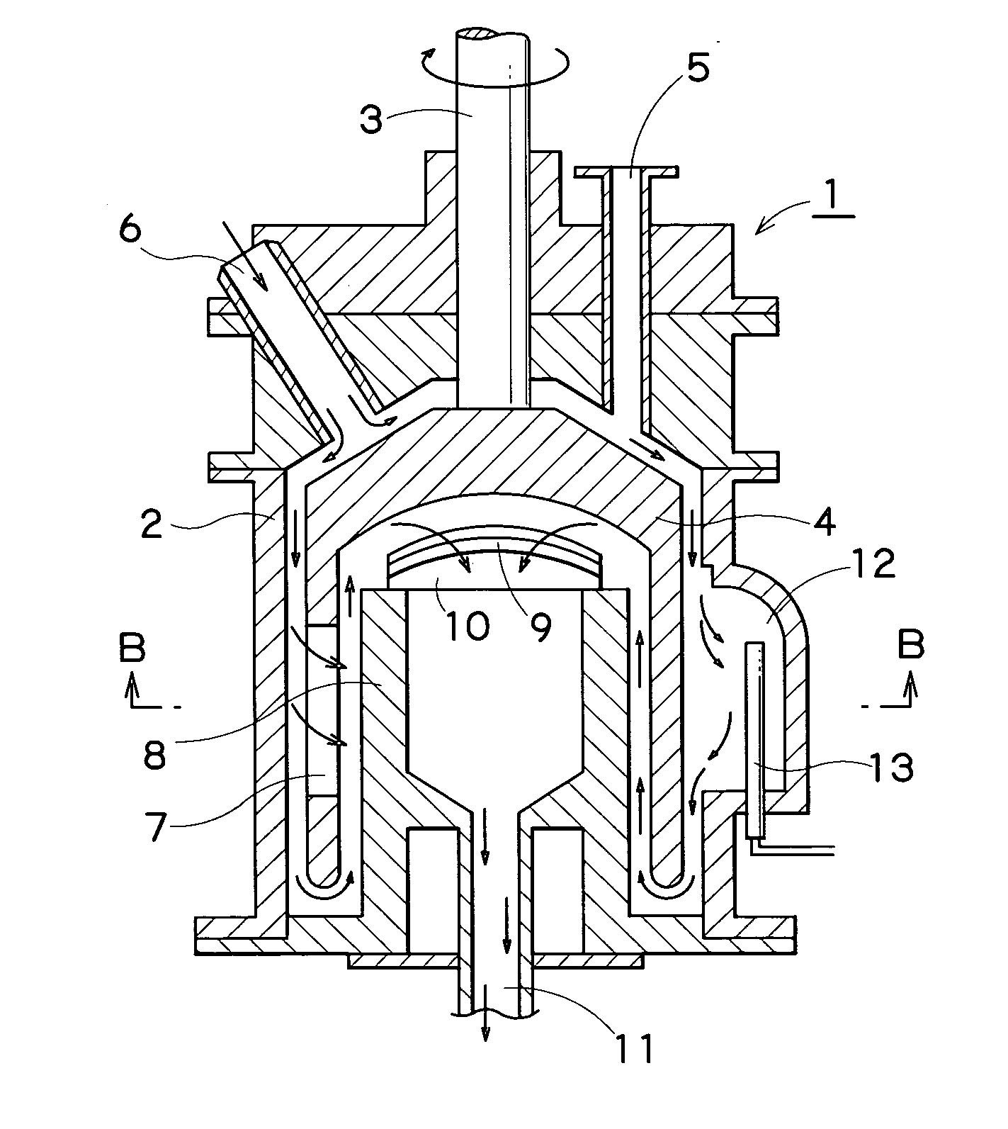
[0051]An apparatus as shown in FIG. 1(A) was used wherein a pocket is formed at a part of a vessel of system A and a horn-type ultrasonic generator was disposed inside the pocket. More specifically, a protruding portion 12 was formed on an inner wall of a vessel 2, and an ultrasonic horn 13 as an ultrasonic-generating device was disposed in the protruding portion 12. The ultrasonic waves had an amplitude of 50 μm and a frequency of 20 KHz. The bead mill was operated at a circumferential speed of 4 m / s and a slurry-supplying rate of 10 mL / s for treatment. An aqueous slurry obtained by adding 10 vol % of P25 powder, i.e., nanoparticulate P25 (Nippon Aerosil Co., Ltd., Tokyo, Japan) with a primary particle size of 35 nm made of titanium oxide nano particles and, as a polymer dispersing agent, polyacrylic acid ammonium salt with a molecular weight of 8,000 added in an amount of 0.5 mg / m2 per surface area of particles, was pre-treated for 30 minutes by using rotating vanes at 500 rpm. Us...

example 2

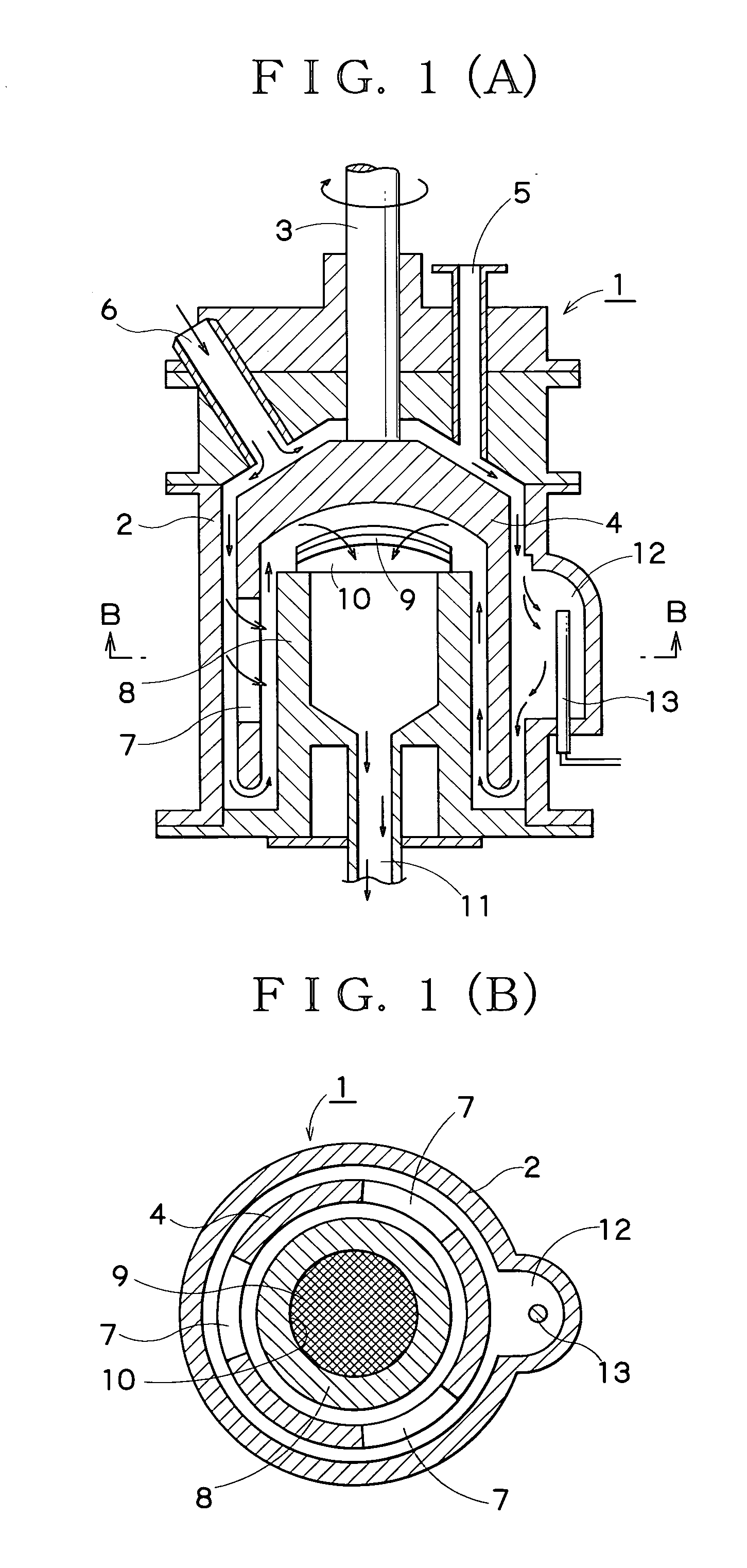
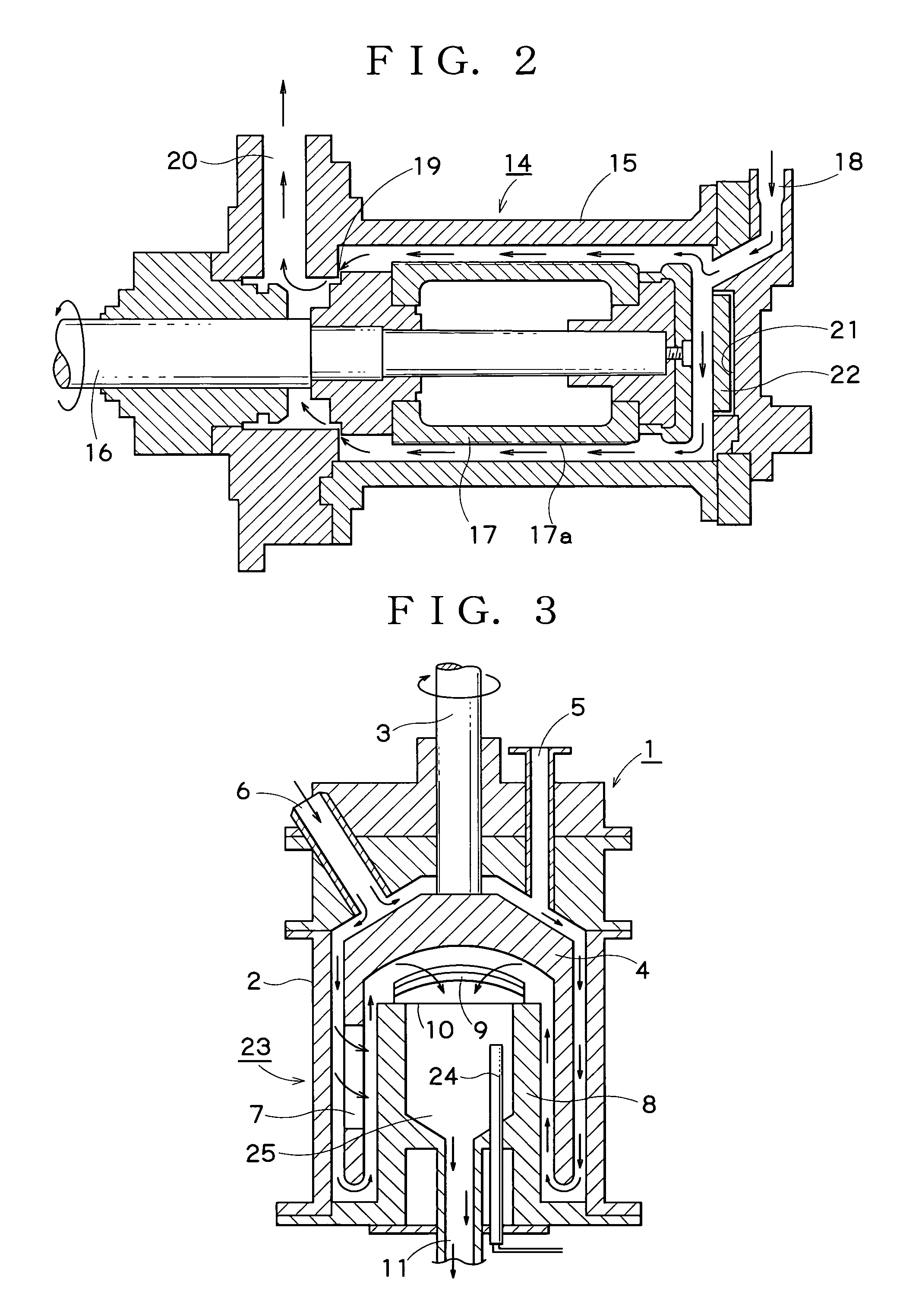
[0052]An apparatus as shown in the FIG. 2 of system B was used. Specifically, a slurry flows from the forward end side of a vessel to a rotor contrary to the slurry flow direction in system A. The experiment of dispersion was conducted in the same manner as in Example 1 using a loading-type ultrasonic generator disposed in a space formed on a side opposite to the forward end of the rotor. Particle sizes measured every hour for 5 hours are indicated in Table 1.

example 3

[0053]An apparatus of system C as shown in FIG. 3 was used. Specifically, a horn-type ultrasonic generator was disposed in a space inside the stator where the slurry accumulates after passing through a screen and before reaching a discharge port. Other than this feature, the same experiment of dispersion as in Example 1 was conducted. Particle sizes, measured hourly for 5 hours, are indicated in Table 1.


PUM

PropertyMeasurementUnit
sizeaaaaaaaaaa
particle sizeaaaaaaaaaa

Abstract

A material to be treated containing solid particles in a liquid is stirred together with milling media, and irradiated with ultrasonic waves during stirring to finely mill the solid particles to nanometer size and disperse the solid particles in the liquid. The ultrasonic waves create cavitation in the liquid and upon decay of the cavitation, shock waves are produced that cause the solid particles to vigorously collide with one another and with the milling media and these collisions, together with the shearing forces created by collision of the milling media, can produce on a commercial scale nano particles having an average particle size of at most 100 nm.

Description

FIELD OF THE INVENTION[0001]The present invention relates to an apparatus and method for dispersing and milling solid particles contained in a liquid to obtain solid particles of nanometer size blended with the liquid.BACKGROUND INFORMATION[0002]Apparatuses for finely milling solid particles in a material to be treated (mill base) by the use of milling media (beads) and dispersing or milling the particles in a liquid, have been known. As such apparatuses, bead mills (wet-type media-dispersing apparatus, media mill, etc.) using beads on the order of millimeter (mm) size as milling media, have been widely used. In apparatuses used for practical production, the material to be treated, which is typically a slurry of solid particles in a liquid, is stirred together with beads, and the solid particles are milled by the shearing action of the beads and dispersed in the liquid to obtain particles finely divided to submicron size.[0003]However, with bead mills using beads of mm size, it is d...

Claims


Application Information

Patent Timeline
Patent Type & Authority Applications(United States)
IPC IPC(8): B02C19/18B02C17/16
CPCB01F3/1221B01F3/1242B01F5/104B02C19/18B01F11/0258B02C17/163B01F7/008B01F23/551B01F23/53B01F25/52B01F27/272B01F31/85B02C17/14B82Y40/00B02C17/24B82B3/0004
Inventor ISHIGAKI, TAKAMASALI, JI-GUANGSATO, KIMITOSHIKAMIYA, HIDEHIROINOUE, YOSHITAKAHATSUGAI, CHOJISUZUKI, TAKASHI
Owner NAT INST FOR MATERIALS SCI
Why Eureka
Try Eureka