Method for manufacturing insulated gate field effect transistor

a technology of field effect transistor and insulated gate, which is applied in the direction of transistors, electrical devices, semiconductor devices, etc., can solve the problems of deterioration of the characteristics of the insulated gate field effect transistor, and achieve the effects of reducing contact resistance, enhancing driving ability of the insulated gate field effect transistor, and lowering the gate capacitan

Active Publication Date: 2008-08-21
SONY CORP
View PDF5 Cites 30 Cited by
  • Summary
  • Abstract
  • Description
  • Claims
  • Application Information

AI Technical Summary

Benefits of technology

[0029]It is desirable that the top surfaces of the source / drain regions be formed of a silicide layer for reduced contact resistance.
[0030]As the base that is used in the manufacturing methods of the present invention and includes the source / drain regions, the channel forming region, and so on, besides a semiconductor substrate such as a silicon semiconductor substrate, a support member of which surface has a semiconductor layer (e.g., a glass substrate, quartz substrate, silicon semiconductor substrate of which surface has an insulating material layer, plastic substrate, or plastic film) can be used. The insulated gate field effect transistor is formed in e.g. a well region or the like in a semiconductor substrate or semiconductor layer. A so-called element isolation region having e.g. a trench structure may be formed between the insulated gate field effect transistors. The element isolation region may have a LOCOS structure, or may be based on the combination of a trench structure and a LOCOS structure. More alternatively, the base having an SOI structure arising from SIMOX or substrate bonding may be used. A known method can be used as a method for preparing the base that includes the source / drain regions, the channel forming region, the gate insulating film formed on the channel forming region, the insulating layer covering the source / drain regions, and the gate electrode formation opening provided in a partial portion of the insulating layer above the channel forming region, i.e., a method for fabricating such a base.
[0031]The term “channel forming region” indicates not only a region in which the channel is actually formed but also a region in which the channel will be possibly formed. For example, partial portions of a semiconductor layer and a semiconductor substrate located to face the gate electrode correspond to the “channel forming region.” Furthermore, the “gate electrode” encompasses not only the electrode portion facing the “channel forming region” but also a lead-out electrode part as an extension from this electrode portion. An insulated gate field effect transistor manufactured by the manufacturing methods of the present invention may be e.g. a CMOS semiconductor device formed of an n-channel MOS and a p-channel MOS, instead of an n-channel MISFET and a p-channel MISFET. Alternatively, it may be a BiCMOS semiconductor device including a bipolar transistor in addition to an n-channel MOS and a p-channel MOS.
[0032]In the manufacturing methods of the present invention, the first interlayer insulating layer and the second interlayer insulating layer are sequentially deposited across the entire surface after the gate electrode is formed. In this deposition, the first interlayer insulating layer is deposited in a deposition atmosphere containing no oxygen atom. This feature can surely prevent the occurrence of a phenomenon of oxidation of a partial portion of the base (e.g., a silicon semiconductor substrate) facing the gate electrode, and thus can surely avoid the occurrence of a problem of the deterioration of characteristics of the insulated gate field effect transistor, such as the lowering of the gate capacitance.
[0033]In the manufacturing method according to the first mode of the present invention, the configuration of the components above the gate electrode (the configuration of the interlayer insulating layers) can be made substantially the same as that of the components above the source / drain regions (the configuration of the insulating layer+the interlayer insulating layers). Thus, the contact plug formation openings can be easily formed for the provision of the contact plugs for the gate electrode and the source / drain regions.
[0034]Furthermore, in the manufacturing methods of the present invention, if the insulating layer is formed of the lower insulating layer and the upper insulating layer, it is possible to make the lower insulating layer function as a liner layer, and thus stress can be applied to the channel forming region. As a result, the driving ability of the insulated gate field effect transistor can be enhanced. Moreover, in the manufacturing method according to the first mode of the present invention, the upper insulating layer is removed whereas the lower insulating layer is left. Therefore, in this insulating layer removal, no damage occurs to the source / drain regions.

Problems solved by technology

The occurrence of such a phenomenon is eventually equivalent to increase in the film thickness of the gate insulating film 30, which results in the deterioration of characteristics of the insulated gate field effect transistor, such as the lowering of the gate capacitance.

Method used


Image

  • Method for manufacturing insulated gate field effect transistor
  • Method for manufacturing insulated gate field effect transistor
  • Method for manufacturing insulated gate field effect transistor

Examples


first embodiment

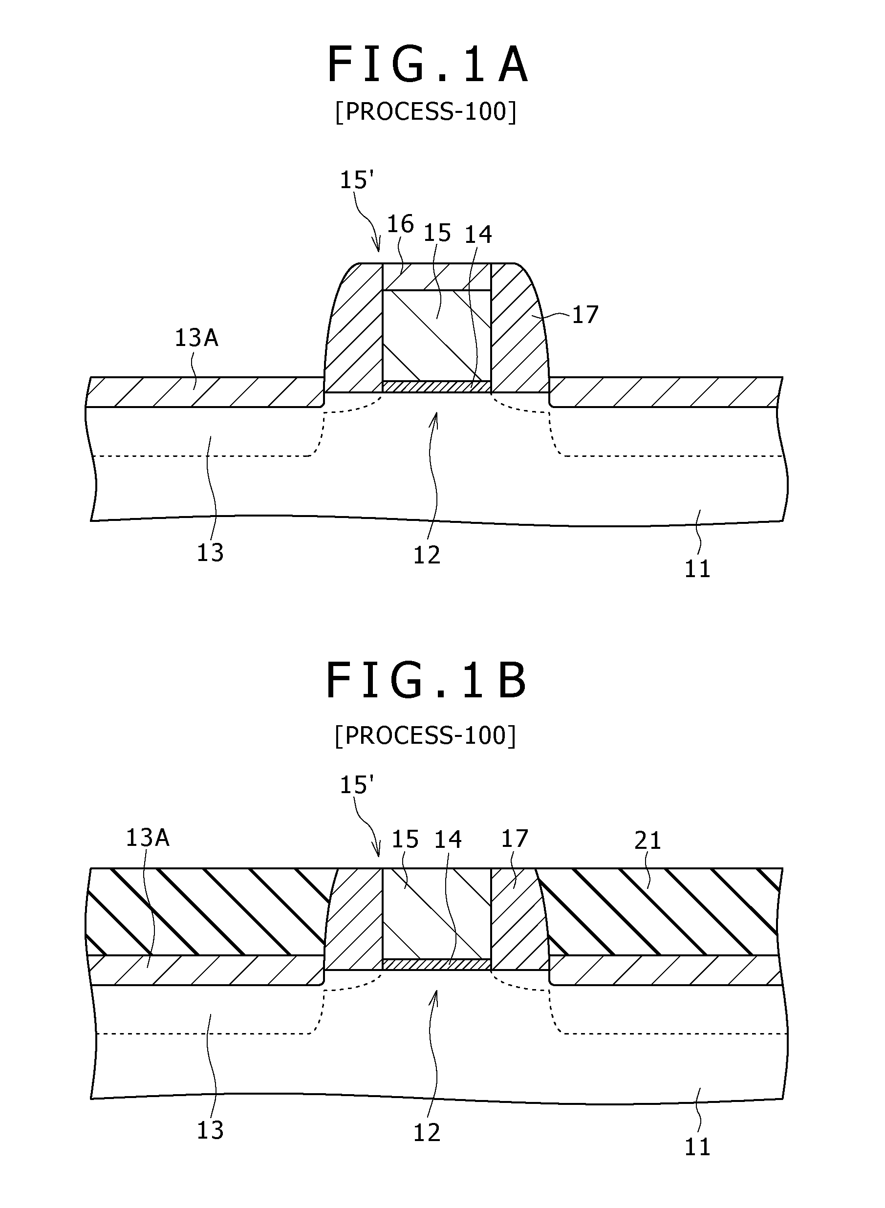
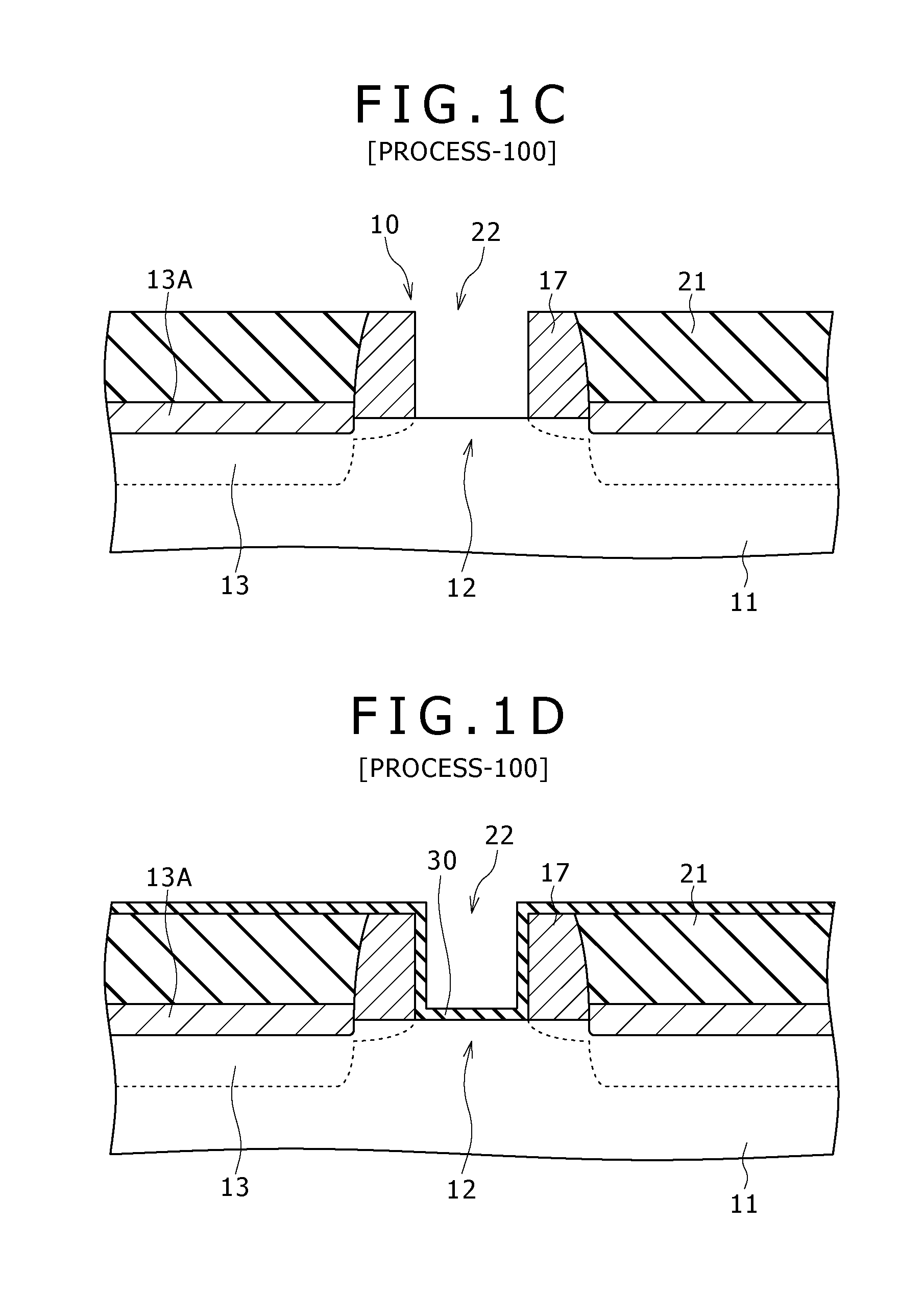
[0041]A first embodiment of the present invention relates to a method for manufacturing an insulated gate field effect transistor according to the first mode of the present invention.

[0042]As shown in the schematic partial end view of FIG. 1I, an insulated gate field effect transistor obtained by the method for manufacturing an insulated gate field effect transistor according to the first embodiment includes (A) source / drain regions 13 and a channel forming region 12, (B) a gate electrode 23 formed above the channel forming region 12, and (C) a gate insulating film 30. In the first embodiment, and in second to fourth embodiments of the present invention, which will be described later, an n-channel insulated gate field effect transistor is formed.

[0043]The gate insulating film 30 is composed of hafnium oxide. The gate electrode 23 is formed of a work function control layer 31 and a conductive material layer 32. The work function control layer 31 is composed of a conductive material (...

second embodiment

[0057]The second embodiment is a modification of the first embodiment. In the second embodiment, the insulating layer is formed of a lower insulating layer 21A and an upper insulating layer 21B formed on this lower insulating layer 21A. The lower insulating layer 21A covers at least the source / drain regions 13 (specifically, the source / drain regions 13 and the side wall film 17). In the step of removing the insulating layer, the upper insulating layer 21B is removed whereas the lower insulating layer 21A is left. The lower insulating layer 21A is composed of the same material as that of the first interlayer insulating layer 41, specifically, SiN. The upper insulating layer 21B is composed of the same material as that of the second interlayer insulating layer 42, specifically, SiOx (X=2). As the film deposition condition for the lower insulating layer 21A composed of SiN, the same condition as that shown in Table 1 can be employed. Examples of the film deposition condition for the up...

third embodiment

[0068]The third embodiment relates to a method for manufacturing an insulated gate field effect transistor according to the second mode of the present invention.

[0069]As shown in the schematic partial end view of FIG. 3B, an insulated gate field effect transistor obtained by the method for manufacturing an insulated gate field effect transistor according to the third embodiment also includes (A) source / drain regions 13 and a channel forming region 12, (B) a gate electrode 23 formed above the channel forming region 12, and (C) a gate insulating film 30.

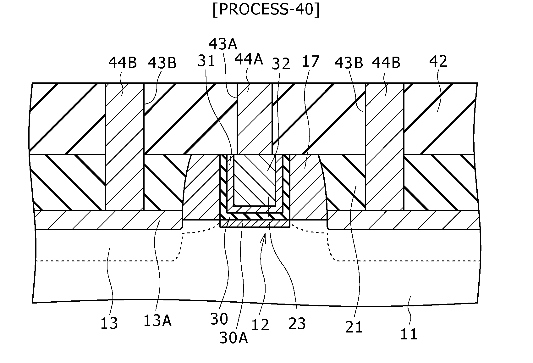
[0070]In the third embodiment, a first interlayer insulating layer 41 composed of silicon nitride (SiN) is deposited (formed) on an insulating layer 21, a side wall film 17, and the gate electrode 23, unlike the first embodiment. On the first interlayer insulating layer 41, a second interlayer insulating layer 42 composed of silicon oxide (SiOx, e.g., X=2) is deposited (formed). Furthermore, a contact plug formation opening 43A is prov...


PUM


Abstract

Disclosed herein is a method for manufacturing an insulated gate field effect transistor, the method including the steps of: (a) preparing a base that includes source/drain regions, a channel forming region, a gate insulating film formed on the channel forming region, an insulating layer covering the source/drain regions, and a gate electrode formation opening provided in a partial portion of the insulating layer above the channel forming region; (b) forming a gate electrode by burying a conductive material layer in the gate electrode formation opening; (c) removing the insulating layer; and (d) depositing a first interlayer insulating layer and a second interlayer insulating layer sequentially across an entire surface, wherein in the step (d), the first interlayer insulating layer is deposited in a deposition atmosphere containing no oxygen atom.

Description

CROSS REFERENCES TO RELATED APPLICATIONS[0001]The present invention contains subject matter related to Japanese Patent Application JP 2007-035007 filed in the Japan Patent Office on Feb. 15, 2007, the entire contents of which being incorporated herein by reference.BACKGROUND OF THE INVENTION[0002]1. Field of the Invention[0003]The present invention relates to a method for manufacturing an insulated gate field effect transistor.[0004]2. Description of the Related Art[0005]Currently, miniaturization of transistors is being advanced based on the so-called scaling rule, and thereby enhancement in the integration degree and the operating speed of semiconductor devices is being promoted. For miniaturization of an insulated gate field effect transistor (metal insulator semiconductor FET (MISFET)), it is demanded to suppress the influence of the so-called short-channel effect. As long as a gate electrode is composed of a semiconductor material, it is difficult to effectively suppress the de...

Claims


Application Information

Patent Timeline
Patent Type & Authority Applications(United States)
IPC IPC(8): H01L21/336H01L29/78
CPCH01L21/28097H01L21/28194H01L2924/0002H01L21/76801H01L21/76832H01L29/4975H01L29/517H01L29/66545H01L29/6659H01L29/66772H01L29/7833H01L29/7843H01L29/78H01L29/4983H01L2924/00
Inventor OKAZAKI, FUMIAKI
Owner SONY CORP
Why Eureka
Try Eureka