Heating apparatus for heating objects to be heated, heating method for heating the objects to be heated, and storage medium in which computer-readable program is stored

a technology for heating objects and heating methods, applied in the field of heating apparatuses for heating objects to be heated, can solve the problems of inability to accurately control the temperature of wafers, the difference between mutual relations, and the increase of the temperature of the wafer, so as to achieve accurate control and high precision temperature control

Active Publication Date: 2008-08-28
TOKYO ELECTRON LTD
View PDF14 Cites 5 Cited by
  • Summary
  • Abstract
  • Description
  • Claims
  • Application Information

AI Technical Summary

Benefits of technology

[0027]According to this invention, the following prominent effects can be obtained. Namely, the transmitter antenna and the receiver antenna are provided to the processing vessel, so as to receive the electric wave generated from the elastic wave element composed of, for example, a langasite substrate element or LTGA or the like, thereby obtaining the temperature of the objects to be processed based on the electric wave. Thus, the temperature of the objects to be processed can be detected securely and accurately, in a wireless and real-time manner, without causing metal contamination or the like, as such providing higher precision temperature control. In addition, because the temperature can also be directly measured upon raising and lowering the objects to be processed, for example, the temperature rising rate and / or temperature lowering rate can be accurately controlled, as such providing more appropriate temperature rising and lowering control. Furthermore, since the temperature of the objects to be processed can be obtained in a wireless manner, a significantly exact temperature of the objects to be processed can be measured even in the case in which films or the like are attached to the inner wall faces of the processing vessel.

Problems solved by technology

Especially, due to attachment of undesired or unwanted deposits onto an inner wall face or the like of the processing vessel after repeated film-forming processes, and / or due to alteration of the gas flow rate and / or processing pressure, and / or due to fluctuation of electric power or the like, a difference from the mutual relation described above may tend to be increased too much, as such making it significantly difficult to appropriately control the wafer temperature.
However, if the thermo-couple as described above is employed in such a case, the difference between the actual wafer temperature and the value to be measured by the thermo-couple is further increased, thus making it quite difficult to respond to such a demand.
However, since the thermo-couple is wired, such a structure can not adapt itself to rotation and / or loading of the wafer.
In addition, due to potential problems of metal contamination or the like attributable to the thermo-couple, such a structure can not be accepted.
However, the heat resistance of the quartz is approximately 300° C. at the most, as such it can not be used for the heating apparatus to be operated under the temperature condition higher than 300° C.

Method used


Image

  • Heating apparatus for heating objects to be heated, heating method for heating the objects to be heated, and storage medium in which computer-readable program is stored
  • Heating apparatus for heating objects to be heated, heating method for heating the objects to be heated, and storage medium in which computer-readable program is stored
  • Heating apparatus for heating objects to be heated, heating method for heating the objects to be heated, and storage medium in which computer-readable program is stored

Examples


examples

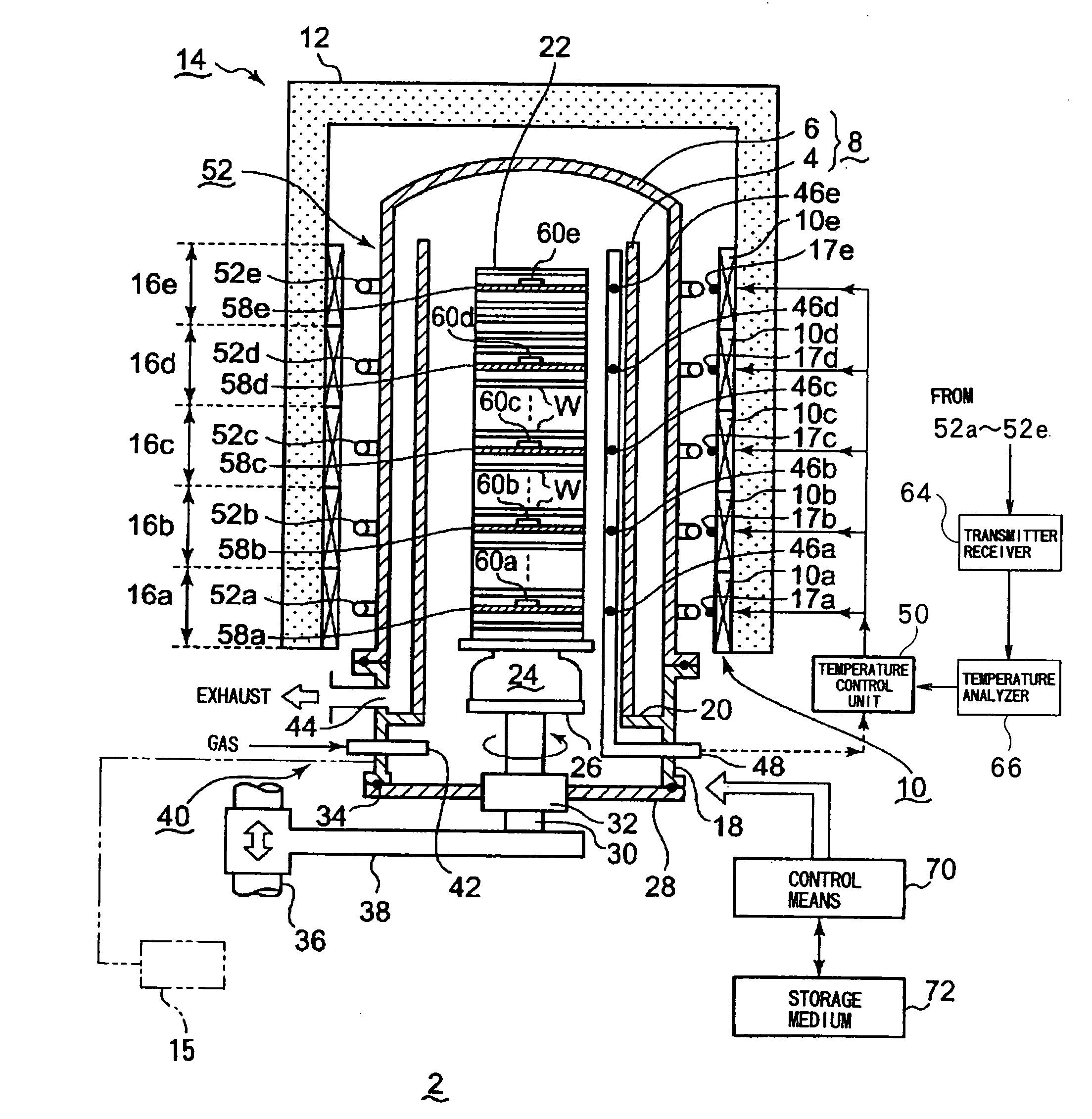
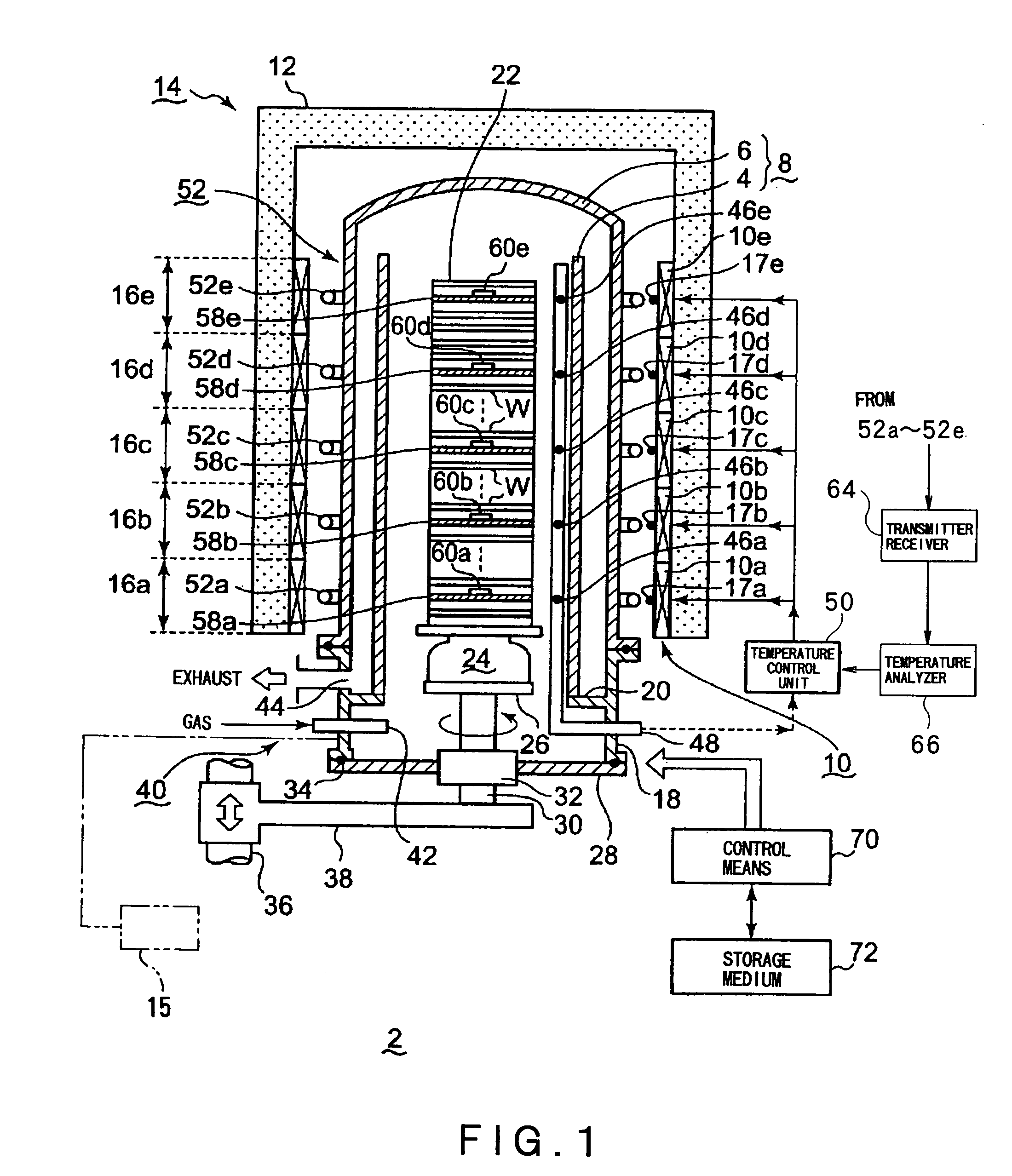
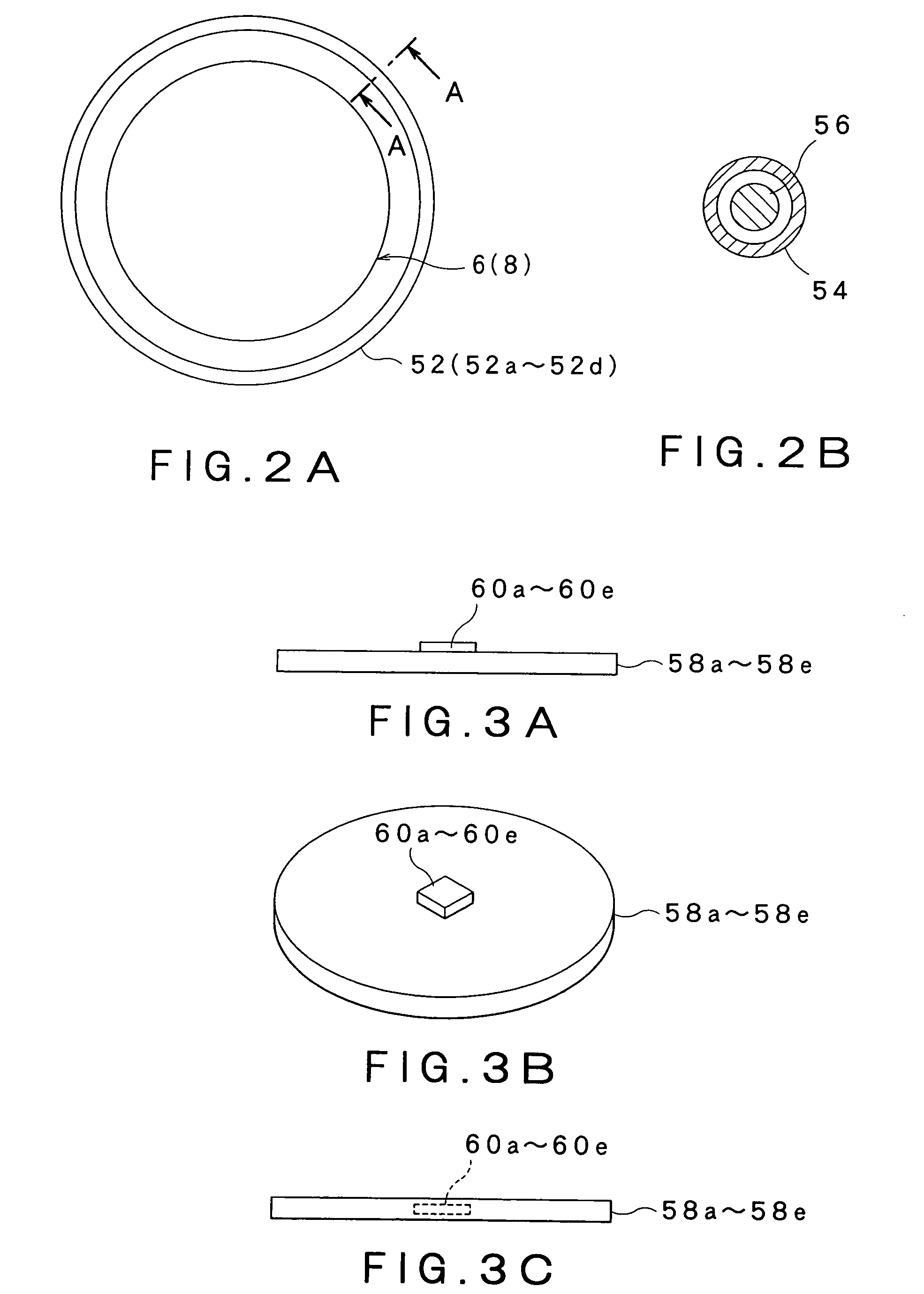
[0039]Hereinafter, one embodiment of the present invention will be detailed with reference to the accompanying drawings. FIG. 1 is a cross-sectional schematic view showing a heating apparatus according to the present invention. FIGS. 2A and 2B are diagrams respectively provided for illustrating a positional relationship between a processing vessel and a looped transmitter-receiver antenna, FIGS. 3A, 3B, and 3C are diagrams respectively provided for illustrating an objected to be processed for temperature measurement, to which an elastic wave element is provided, FIG. 4 is a schematic diagram showing a temperature control system of the heating apparatus, FIG. 5 is a flow-chart showing one example of a heating method of the present invention, and FIGS. 6A and 6B are diagrams showing a principle of operation for explaining the principle of operation of the elastic wave element.

[0040]In the description below, a case in which a transmitter-receiver antenna formed by combining a transmitt...


PUM

PropertyMeasurementUnit
temperatureaaaaaaaaaa
heat resistanceaaaaaaaaaa
diameteraaaaaaaaaa

Abstract

The present invention provides a heating apparatus for heating objects to be processed, which can detect a temperature of the objects to be processed with higher precision and accuracy, thereby to achieve higher precision temperature control. A heating apparatus 2 includes a processing vessel 8 configured to contain therein a plurality of objects W to be processed, the objects W including objects 58a to 58e to be processed for temperature measurement, each object 58a to 58e having each corresponding elastic wave element 60a to 60e, a heating means 10 adapted for heating the objects W to be processed, and a holding means 22 adapted to hold the objects W to be processed. To the processing vessel 8, a transmitter antenna 52 adapted to transmit an electric wave for measurement toward each elastic wave element 60a to 60e, and a receiver antenna 52 adapted to receive an electric wave having a frequency corresponding to the temperature and generated from each elastic wave element 60a to 60e are provided. A temperature analyzer 66 adapted to obtain the temperature of the wafers W to be processed for temperature measurement is connected with the receiver antenna 52, and a temperature control unit 64 adapted to control the heating means 10 is in turn connected with the temperature analyzer 66.

Description

CROSS REFERENCE TO RELATED APPLICATIONS[0001]This application is based upon the prior Japanese Patent Application No. 2007-048125 filed on Feb. 27, 2007, and Japanese Patent Application No. 2008-033579 filed on Feb. 14, 2008, the entire contents of which are incorporated herein by reference.BACKGROUND OF THE INVENTION[0002]1. Field of the Invention[0003]The present invention relates to a heating apparatus for heating objects to be heated, such as semiconductor wafers or the like, in order to provide a heating process to the objects to be processed, and also relates to a heating method for heating the object to be processed and to a storage medium in which a computer-readable program is stored.[0004]2. Background Art[0005]In general, upon forming semiconductor integrated circuits, such as ICs or the like, various processes, such as film-forming, etching, oxidation and diffusion, annealing and the like, are repeatedly provided to each semiconductor wafer composed of a silicon substrat...

Claims


Application Information

Patent Timeline
Patent Type & Authority Applications(United States)
IPC IPC(8): F27D11/00
CPCF27B17/0025H01L21/67248H01L21/67109
Inventor YAMAGA, KENICHI
Owner TOKYO ELECTRON LTD
Why Eureka
Try Eureka