Multiple light-emitting element heat pipe assembly

a technology of heat pipe and light-emitting elements, which is applied in the direction of lighting and heating apparatus, printing, instruments, etc., can solve the problems of large amount of waste heat, excessive heat release under operating conditions, and limited applicability of form and us

Inactive Publication Date: 2008-08-28
TIR TECH LP
View PDF99 Cites 50 Cited by
  • Summary
  • Abstract
  • Description
  • Claims
  • Application Information

AI Technical Summary

Benefits of technology

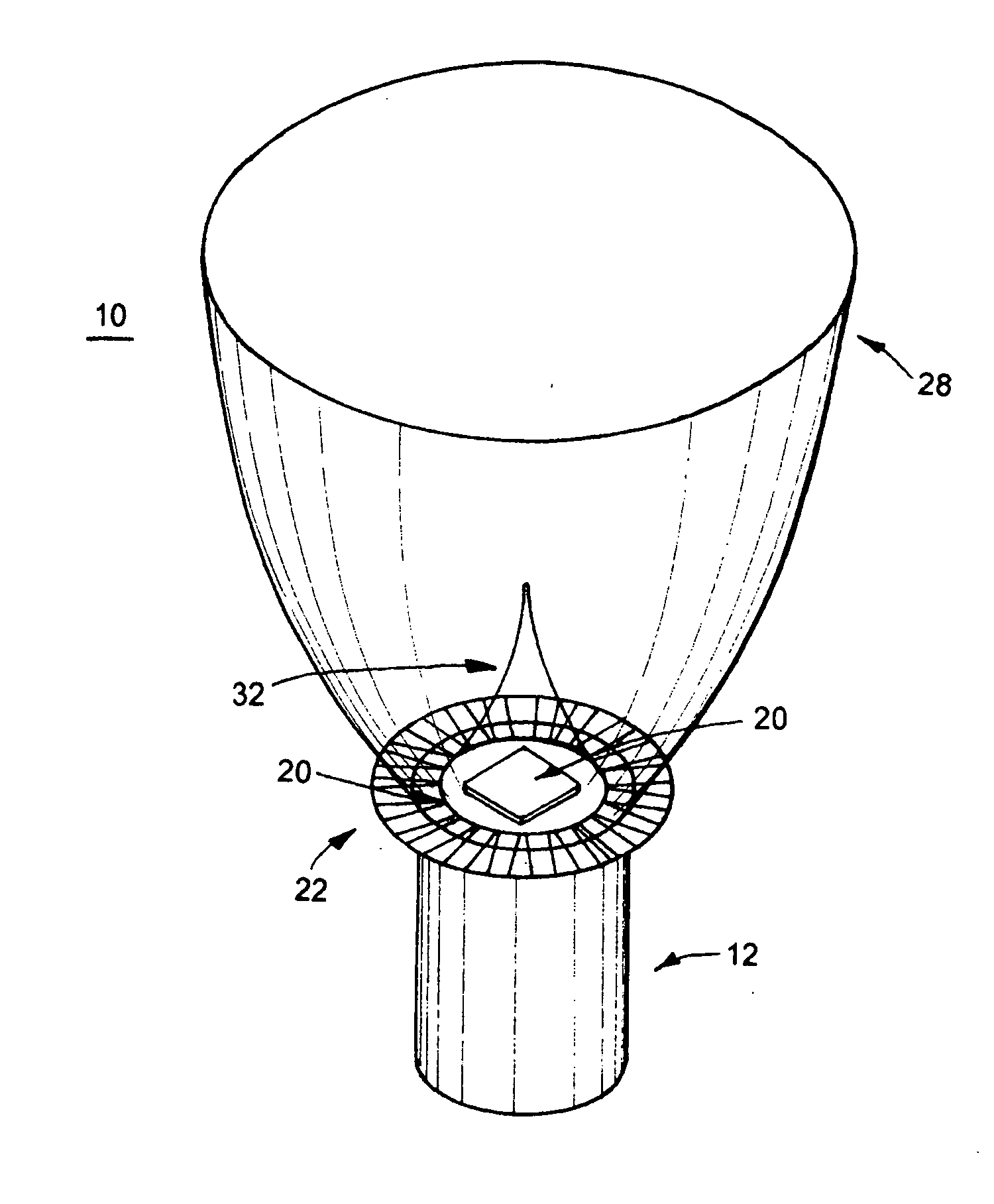
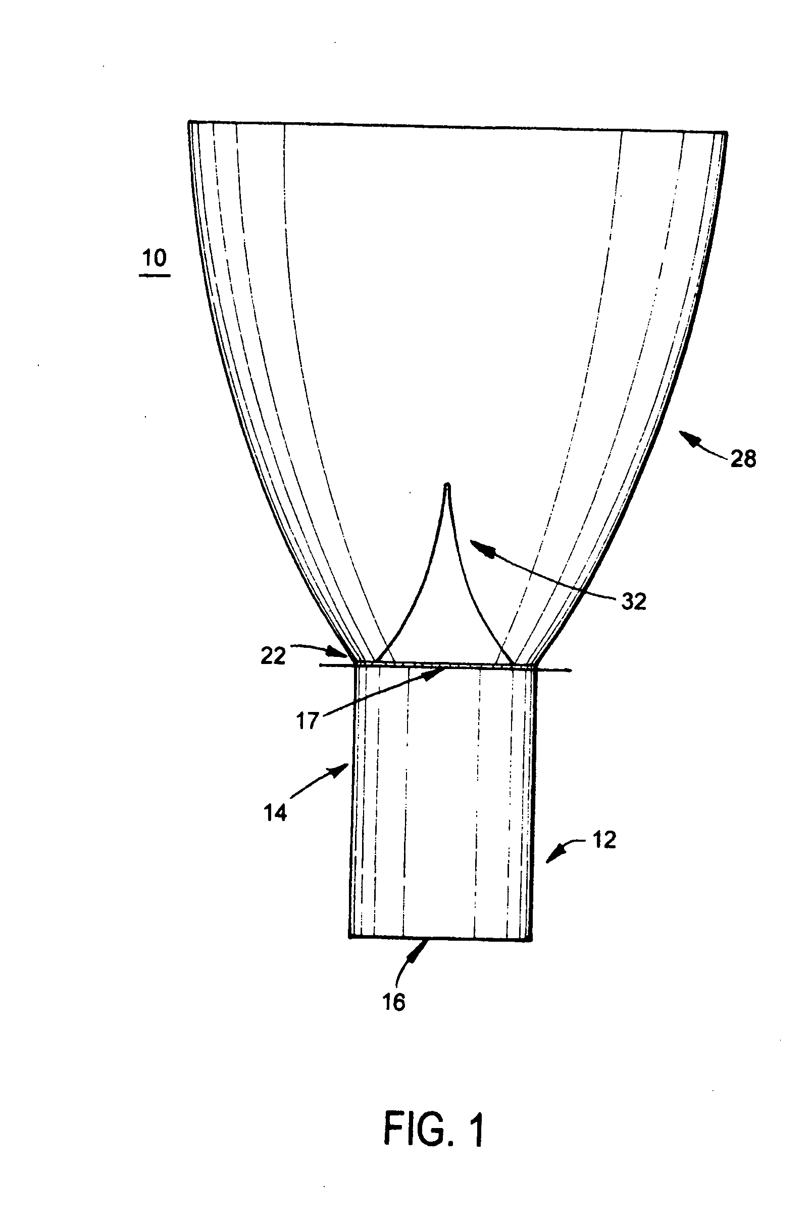
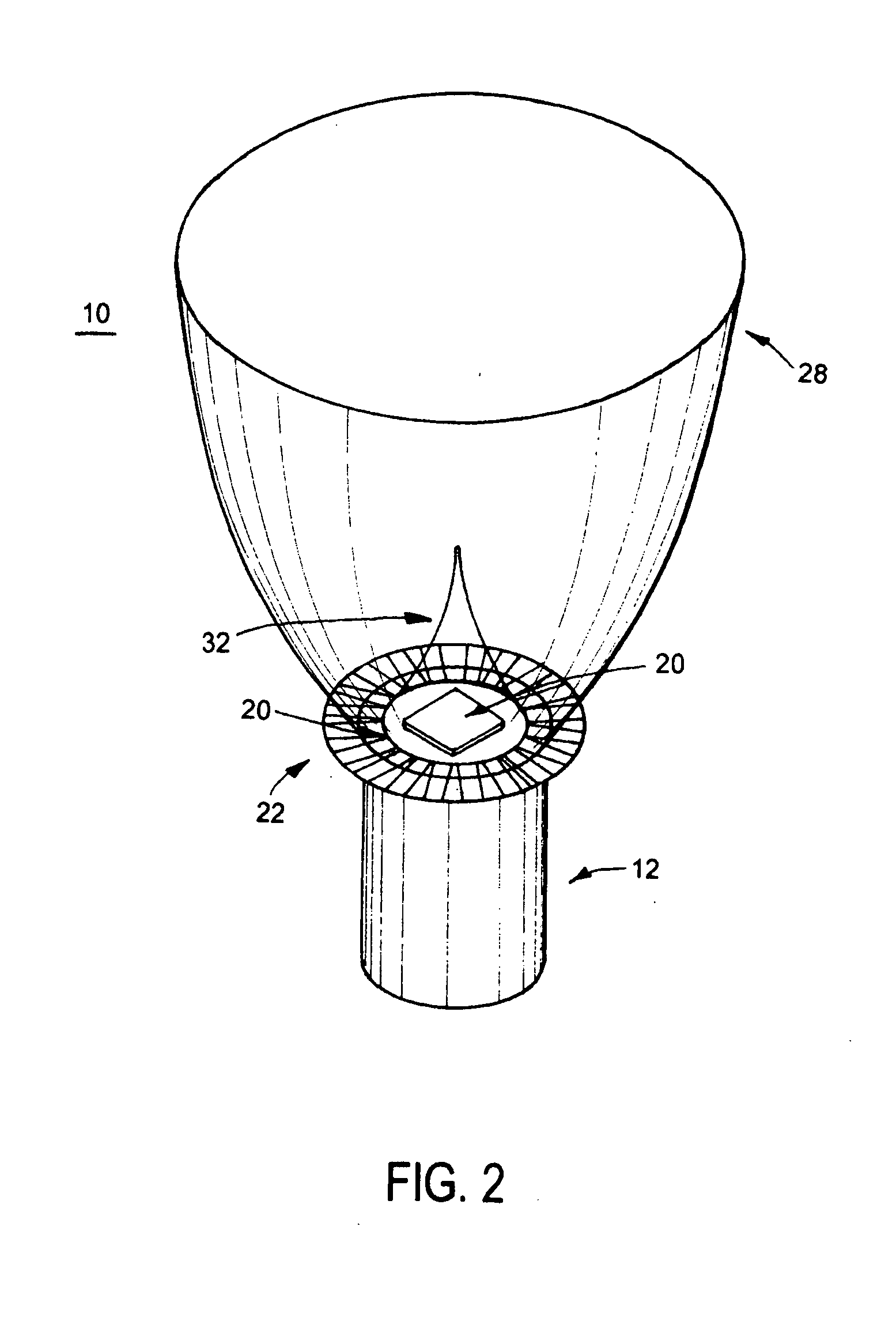
[0011]An object of the present invention is to provide a multiple light-emitting element heat pipe assembly. In accordance with one aspect of the present invention, there is provided an optical device comprising: a heat pipe having an evaporator end portion having a perimeter; one or more light-emitting elements for generating light, the one or more light-emitting elements operatively and thermally coupled to the heat pipe at the perimeter of the evaporator end portion.
[0012]In accordance with another aspect of the present invention, there is provided an optical device comprising: a plurality of heat pipes each having a evaporat

Problems solved by technology

A general drawback of high-brightness light sources includes the release of excessive quantities of heat under operating conditions.
While being relatively efficient certain LEDs offer high energy densities and generate large amounts of waste heat in small spaces.
Heat sinks are widely employed for the thermal management of luminaries but their form and use have limited applicability for the direct cooling of LEDs as interferences with the light emission of the LEDs are usually undesired.
Heat sinks provide limited heat dispersion capabilities and occupy relatively large spaces in order to work effectively.
Heat sinks can only be employed where they can be adequately thermally coupled to LEDs or other heat sources and may therefore be excluded from use in systems with high device integration densities.
Many known he

Method used


Image

  • Multiple light-emitting element heat pipe assembly
  • Multiple light-emitting element heat pipe assembly
  • Multiple light-emitting element heat pipe assembly

Examples


Embodiment Construction

Definitions

[0036]The term “light-emitting diode” (LED) is used to include a general or specific type of LED or laser diode such as resonant cavity LED (RCLED), superluminescent LED (SLLED), organic LED (OLED), flexible OLED (FOLED), Flip Chip LED (FCLED), high-brightness LED or other LED as would be readily understood by a worker skilled in the art.

[0037]The term “light-emitting element” (LEE) is used to define a device that emits radiation in a region or combination of regions of the electromagnetic spectrum for example, the visible region, infrared and / or ultraviolet region, when activated by applying a potential difference across it or passing a current through it, for example. Therefore a light-emitting element can have monochromatic, quasi-monochromatic, polychromatic or broadband spectral emission characteristics. Examples of light-emitting elements include semiconductor, organic, or polymer / polymeric light-emitting diodes, optically pumped phosphor coated light-emitting diode...


PUM


Abstract

The present invention provides an optical device comprising one or more heat pipes with a desired level of thermal coupling with the light-emitting elements which are positioned along a periphery of the evaporator surface portion of the heat pipe in such a way that they are thermally coupled to the heat pipe. In one embodiment, the heat pipe of the present invention can be readily integrated with optical elements such as reflectors or collimators.

Description

FIELD OF THE INVENTION[0001]The present invention pertains to thermal management of light-emitting elements and more particularly to an assembly comprising one or more heat pipes for thermal management of multiple light-emitting elements.BACKGROUND[0002]Luminaires are employed in a number of lighting applications, such as ambient or space lighting, accent lighting, wall washing, signage, advertising, decorative and display lighting, façade lighting, and custom lighting. Luminaires typically include a number of high-brightness incandescent, fluorescent, neon, or light-emitting diode (LEDs) type light sources coupled to a power management system for supply of energy and control of the desired utility.[0003]A general drawback of high-brightness light sources includes the release of excessive quantities of heat under operating conditions. While being relatively efficient certain LEDs offer high energy densities and generate large amounts of waste heat in small spaces. The use of high-br...

Claims


Application Information

Patent Timeline
IPC IPC(8): F21V29/00F21V29/505
CPCH01L33/648F21K9/00F21V29/004F21V29/006F28D15/0233F21V29/773H01L23/427H01L2924/0002F28D15/0266F21V29/74H01L2924/00F21V29/51F21V29/83F21K9/68
Inventor DAHM, JONATHAN S.JONGEWAARD, MARK PAUL
Owner TIR TECH LP
Why Eureka
Try Eureka