Electron gun, electron beam exposure apparatus, and exposure method

a technology of electron beam and exposure apparatus, which is applied in the direction of discharge tube electron guns, electrical devices, electric discharge tubes, etc., can solve the problems of unstable amount and irradiation position of electron beams, troublesome control of exposure systems, and unstable throughput, so as to prevent the melting or damage of electron sources

Inactive Publication Date: 2008-09-04
ADVANTEST CORP
View PDF2 Cites 27 Cited by
  • Summary
  • Abstract
  • Description
  • Claims
  • Application Information

AI Technical Summary

Benefits of technology

[0022]In the present invention, at the time of conditioning before exposure, the potential of the extraction electrode is set to be lower than that of the electron sourc...

Problems solved by technology

Moreover, if an exposure time is increased to supplement the weakened intensity, control of the exposure system becomes troublesome, and the throughput is deteriorated.
If such micro discharge is caused, a phenomenon is caused that the amount and irradiation position of an electron beam are unstable, and that the electron beam exposure apparatus cannot be used normally.
Further...

Method used


Image

  • Electron gun, electron beam exposure apparatus, and exposure method
  • Electron gun, electron beam exposure apparatus, and exposure method
  • Electron gun, electron beam exposure apparatus, and exposure method

Examples


Embodiment Construction

[0033]A preferred embodiment of the present invention will be described below by referring to the drawings.

[0034]Firstly, the configuration of an electron beam exposure apparatus will be described. Subsequently, the configuration of an electron gun will be described, and then the configuration of an electron source of the electron gun, which is a characteristic feature of the present invention, will be described. Thereafter, an exposure method of the exposure apparatus using the electron gun of the present invention will be described. Then, a method for forming, on a surface of the electron source, a region which restricts electron distribution will be described. Lastly, effects of a case where the electron gun according to the present embodiment is used will be described.

(Configuration of the Electron Beam Exposure Apparatus)

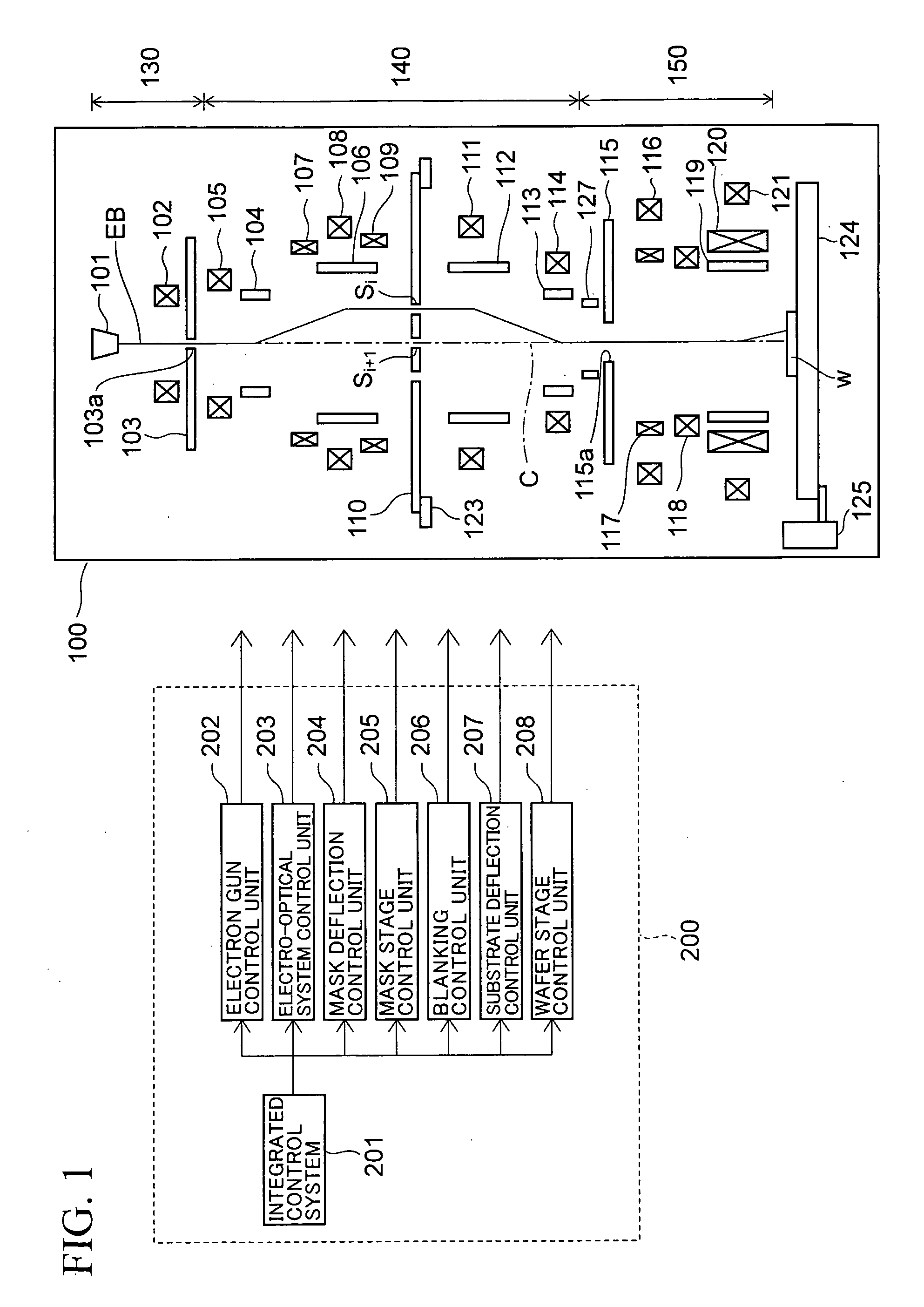
[0035]FIG. 1 shows a configurational view of an electron beam exposure apparatus according to the present embodiment.

[0036]This electron beam exposure apparatu...


PUM


Abstract

An electron gun having an electron source emitting electrons includes: an acceleration electrode which accelerates the electrons; an extraction electrode which has a spherical concave surface having the center on an optical axis and facing the electron emission surface, and which extracts an electron from the electron emission surface; and a suppressor electrode which suppresses electron emission from a side surface of the electron source. In the electron gun, an electric field is applied to the electron emission surface while the electron source is kept at a low temperature in such an extent that sublimation of a material of the electron source would not be caused, to cause the electron source to emit a thermal field emission electron.

Description

CROSS-REFERENCE TO RELATED APPLICATIONS[0001]This application is a continuation of prior International Patent Application No. PCT / JP2007 / 053101, filed Feb. 20, 2007, the entire contents of which are incorporated herein by reference.BACKGROUND OF THE INVENTION[0002]1. Field of the Invention[0003]The present invention relates to an electron gun used in a lithography process for manufacturing a semiconductor device, an electron beam exposure apparatus provided with the electron gun, and an exposure method.[0004]2. Description of the Prior Art[0005]Recently, in order to improve the throughput in electron beam exposure apparatus, a variable rectangular opening or a plurality of mask patterns is prepared as a mask, and thus a pattern is selected by beam deflection to be transferred through exposure onto a wafer. As one of exposure methods using such a plurality of mask patterns, proposed is an electron beam exposure apparatus which carries out block exposure. In the block exposure, a patt...

Claims


Application Information

Patent Timeline
IPC IPC(8): H01J29/48
CPCB82Y10/00B82Y40/00H01J3/02H01J2237/06316H01J37/063H01J37/075H01J37/3174H01J29/48
Inventor YASUDA, HIROSHIHARAGUCHI, TAKESHI
Owner ADVANTEST CORP
Why Eureka
Try Eureka