
Micromachined Acoustic Transducers

Inactive Publication Date: 2008-09-04
GENERAL MEMS CORP
View PDF15 Cites 18 Cited by
  • Summary
  • Abstract
  • Description
  • Claims
  • Application Information

AI Technical Summary

Benefits of technology

[0014]An object of this invention is to provide transducers that produce high quality sounds at low frequencies and at high intensities.
[0017]Another object of this invention is to provide transducers that can be mass produced easily and inexpensively.
[0020]An advantage of the transducers of this invention is that they can produce high quality sounds at low frequencies and at high intensities.
[0021]Another advantage of the transducers of this invention is that they can radiate sounds uni-directionally.
[0023]Another advantage of the transducers of this invention is that they can be micromachined using conventional integrated circuit manufacturing processes and therefore can be mass produced easily and inexpensively.

Problems solved by technology

The high bias voltage needed to operate these actuators may pose safety hazards for end applications.
In addition, the large diaphragm deflection can easily result in diaphragm fatigue, causing reliability concerns.
However, in their manufacture and operation, these transducers do not provide any advantage over other devices made with traditional technology.
These piezoelectric microspeakers suffer from low output sound pressure level and poor frequency response when compared with traditional magnetically driven speakers.
Although applying electric fields to the driver elements with constrained piezoelectric membrane or ceramics elements in these devices can produce large forces, the resulting strain is relatively small.
Therefore, it is difficult to obtain the large vibrational amplitudes needed for high intensity and low frequency sound with piezoelectric devices.
This limits the energy transfer efficiency of piezoelectric electro-acoustic devices designed for use in air, such as loudspeakers.
Although the low frequency performance of this transducer is superior to other conventional piezoelectric drive arrangements, the intensity of sound that can be radiated is limited.
Moreover, for these transducers, the directionality of the sound can not be controlled; their radiating area is relatively small; and, their bandwidth is relatively narrow.
Impedance mismatches render this type of element unsuitable for use in air.
When used in ordinary loudspeakers, these transducers are expensive to manufacture and their enclosures difficult to design.
It is also difficult to eliminate the effect of cancellation between positive and negative pressures at low frequencies where the wavelengths generated are greater than the size of the enclosure.
Moreover, the manufacturing process for this type of device usually requires the potting of organic materials and is difficult to control.
Therefore, it is difficult to maintain the quality of this device during manufacturing.
In addition, this transducer panel can not withstand high re-flow temperature, a necessary condition for automatic assembly.
However, for micromachined devices, the diaphragm movement is typically limited to a few microns.

Method used


Image

  • Micromachined Acoustic Transducers
  • Micromachined Acoustic Transducers
  • Micromachined Acoustic Transducers

Examples


Embodiment Construction

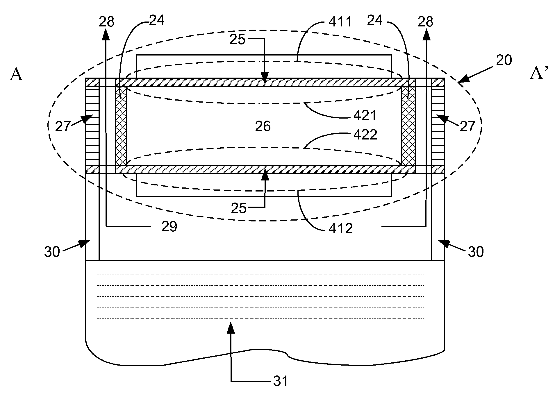
[0053]presently preferred embodiments provide transducers for sound generation and n that may contain one or more capsules arranged in a scalable array, in either one or two dimensions. In certain preferred embodiments, the capsules may be sealed. Each capsule may form an acoustic monopole. For example, each capsule may contain a pair of film stacks that faces each other and side walls such that the film stacks and the side walls form a cavity. Each film stack may contain one or more layers or material of which at least one is a membrane that may be a piezoelectric layer. Some of these layers of material may be layers of conducting material, referred herein as conductors. Preferably, the piezoelectric layer is sandwiched between the conducting layers. The surface of the film stack that is substantially aligned with the surfaces of said one of more layers of material is referred to herein as the face of the film stack. In the preferred embodiments, the film stacks containing the piez...


PUM


Abstract

The present invention relates to an acoustic transducer that includes one or more capsules, side walls and a backing plate. Each capsule contains a cavity formed by the side walls and a plurality of film stacks. Each film stack has one or more membranes that can be a piezoelectric layer. Two or more of the film stacks that form the first cavity faces each other. A film stack and the backing plate face each other and form the wall of a second cavity. The transducers of this invention have a broadband response, can radiate sounds uni-directionally, and produce high quality sounds at low frequencies and at high intensities. They can be driven by AC signals. They can be fabricated using conventional integrated circuit manufacturing processes and therefore can be mass produced easily and inexpensively.

Description

FIELD OF INVENTION[0001]The present invention relates to microelectromechanical microphones, and in particular, to microelectromechanical microphones using piezoelectric material.BACKGROUND[0002]The micromachining technology that has led to the advancement of many micromachined acoustic devices has mostly focused on the development of microphones for converting acoustic signals to electrical signals that need further processing and reproduction. Some efforts have also been made to develop acoustic actuators that can operate in the ultrasonic range, such as capacitive micromachined ultrasonic transducers (CMUTs) that operate in the MHz or even higher frequency ranges. For example, U.S. patents with U.S. Pat. Nos. 5,619,476, 5,870,351, 5,894,452, and 6,493,288 describe the fabrication of capacitive-type ultrasonic transducers where membranes are supported above a substrate by insulative supports such as silicon nitride, silicon oxide, and polyamide. These supports engage the edges of ...

Claims


Application Information

Patent Timeline
IPC IPC(8): H04R17/10
CPCH04R1/227H04R19/005H04R17/00
Inventor WANG, YUNLONG
Owner GENERAL MEMS CORP
Learn More