RF power amplifier protection

a power amplifier and protection technology, applied in amplifier protection circuit arrangements, amplifiers with semiconductor devices only, amplifiers with semiconductor devices, etc., can solve the problems of destroying (burning out) the rf power device, common drive level limitation in constant envelope power amplifiers, and the lik

Inactive Publication Date: 2008-09-11
MOTOROLA SOLUTIONS INC
View PDF5 Cites 28 Cited by
  • Summary
  • Abstract
  • Description
  • Claims
  • Application Information

AI Technical Summary

Problems solved by technology

This is a particular problem at the even harmonics, where the Class AB bias tends to generate strong even harmonic currents, as noted above.
When this happens, the high avalanche current produced by drain-source junction breakdown can destroy (burnout) the RF power device.
This drive level limitation is common in constant envelope (FM) power amplifiers, where linearity is not required.
Experience has shown that the techniques described in U.S. patent application Ser. No. 11/345,573 may be inadequate to prevent RF power device burnout in the event of such a severe overdrive.
One such “runaway” condition can arise if the feedback phase shift in a Cartesian feedback linearizer is set incorrectly, which can be caused by a hardware or software failure during the training process used to pre-align this phase shift.
In this case, burnout can occur when this overdrive causes the instantaneous drain voltage of an RF power transistor to exceed its breakdown voltage.
Currently, there exists no suitable method for the application designer to address th...

Method used


Image

  • RF power amplifier protection
  • RF power amplifier protection
  • RF power amplifier protection

Examples


Embodiment Construction

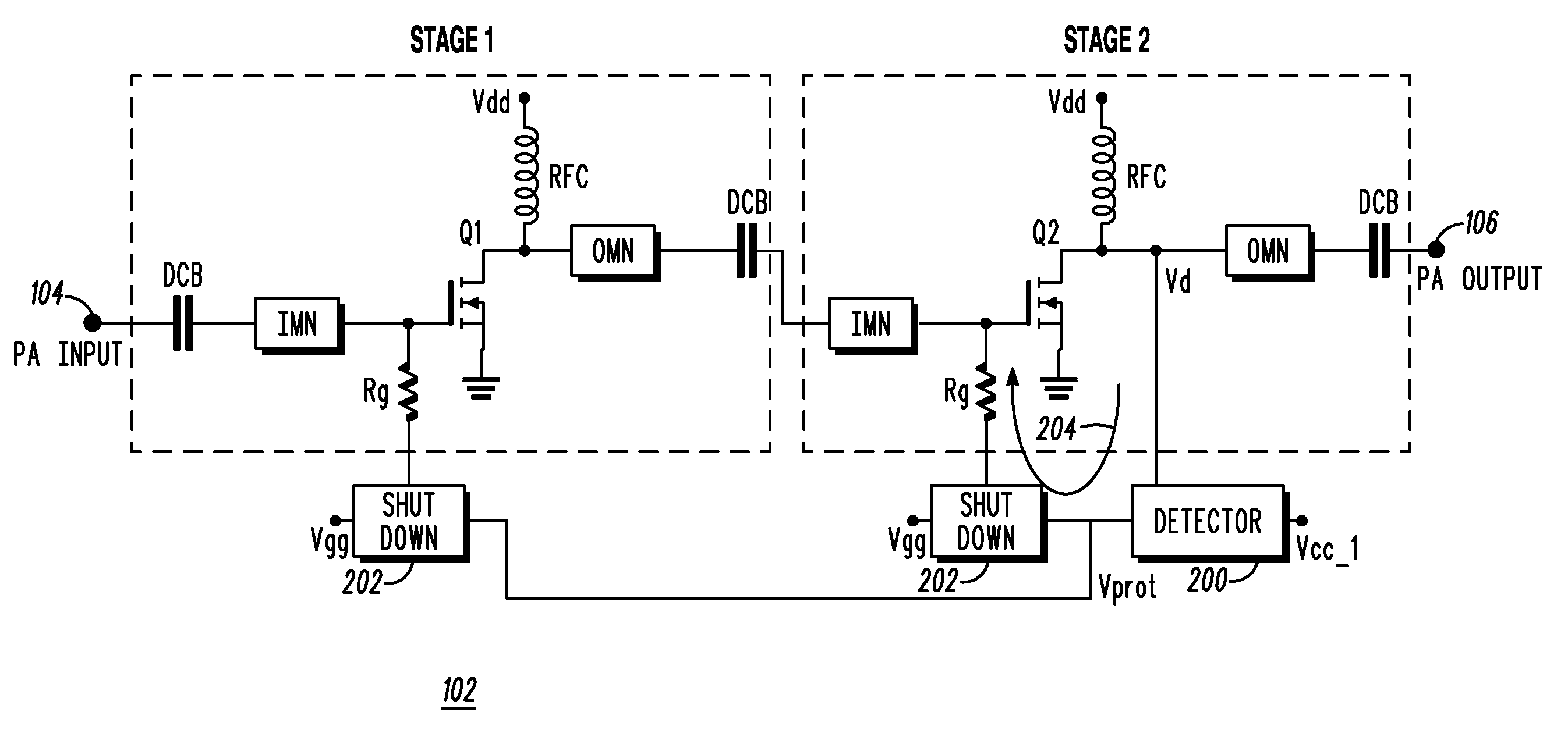
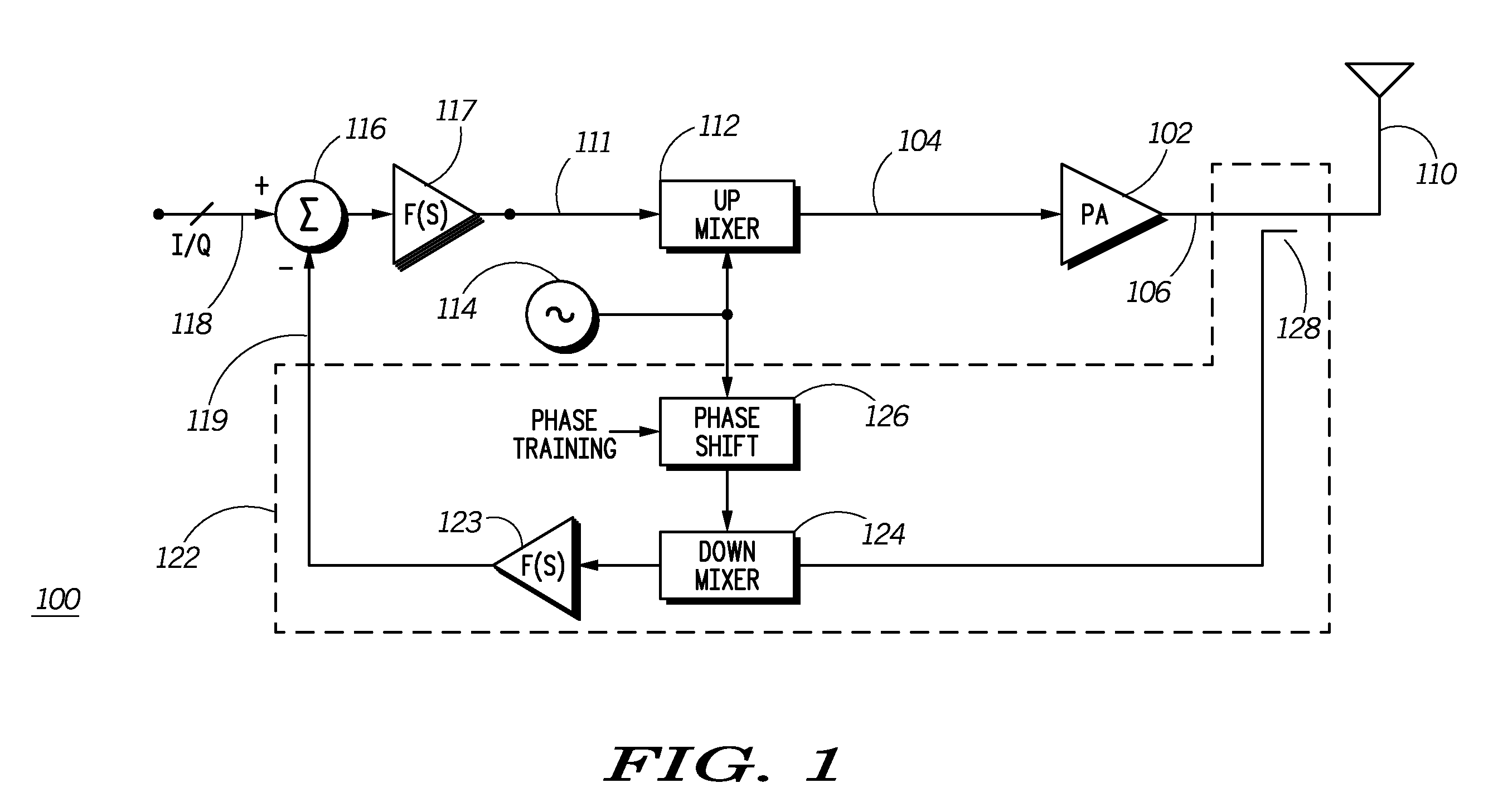
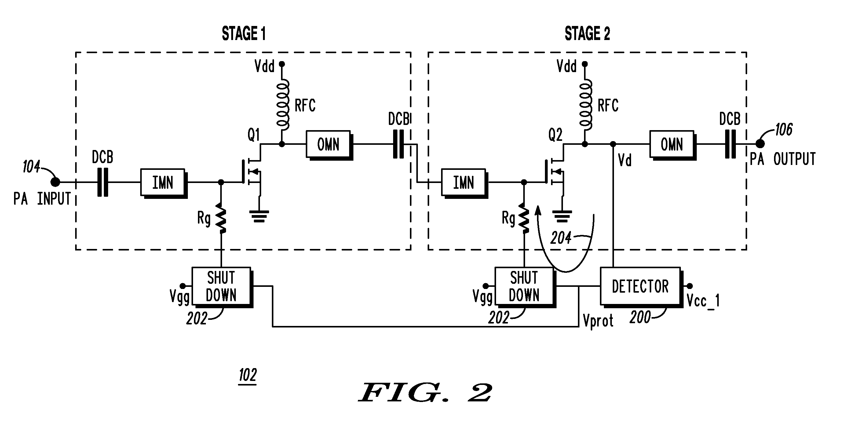
[0024]Generally, the present invention provides a method and apparatus which protects a power amplifier from destructive operating conditions which may arise as the result of severe overdrive of a transistor amplifier. The protection is accomplished by directly sensing the drain voltage, comparing the level to a predetermined reference, and, in the event the reference is exceeded, removing the gate bias applied to the amplifier elements. The present invention responds fast enough to prevent the transistor output voltage from ever reaching the breakdown voltage of the transistor. Once triggered, the transistor is kept off for a period of time sufficiently long enough to insure that the transmitter senses a problem and resets itself. A novel aspect of the invention having the detector connection directly at the transistor output lead, as opposed to the prior art which sense at the output of the amplifier stage or module, a point at which the voltage waveform is less rich in harmonic c...


PUM


Abstract

A circuit and method for protecting a radio frequency power amplifier against peak drain voltage. A detector circuit has an input connected to a drain of a power transistor of an amplification stage of the power amplifier to detect a peak drain voltage therefrom. The detector circuit outputs a protection signal when the detected peak drain voltage exceeds a predetermined reference level. A shutdown circuit is coupled to the detector circuit and inputs the protection signal therefrom. The protection signal is used to remove a gate bias of at least one amplification stage of the power amplifier. High frequency components are used in the detector and protection circuits to immediately reduce the drain voltage from one or more of the amplification stages.

Description

FIELD OF THE INVENTION[0001]The present invention relates generally to protection of power amplifiers and, in particular, to protection of power amplifiers from excessive operating power levels.BACKGROUND OF THE INVENTION[0002]Power amplifiers are used in transmitters to rebroadcast, at high power levels, amplitude modulation (AM) signals, frequency modulation (FM) signals, and quadrature amplitude modulation (QAM) signals. As is known, information is carried in the amplitudes of AM and QAM signals. Because of this, transmitters must accurately rebroadcast these signals, thus the power amplifiers within the transmitters must have high fidelity, i.e. linearly rebroadcast the signals they receive.[0003]A typical linear transmitter includes a baseband signal generator that produces a baseband signal output in response to a digital input. The digital input is mapped to a constellation corresponding to output voltage level and phase. An example of such a modulation is QAM. The baseband s...

Claims


Application Information

Patent Timeline
IPC IPC(8): H03F1/52
CPCH04B1/0466H03F1/523H03F1/0272
Inventor MITZLAFF, JAMES E.ROBIN, JOSEPH F.
Owner MOTOROLA SOLUTIONS INC
Why Eureka
Try Eureka