Gas Turbine Engine Components With Aluminide Coatings And Method Of Forming Such Aluminide Coatings On Gas Turbine Engine Components

a technology of gas turbine engine and aluminide coating, which is applied in the direction of liquid/solution decomposition chemical coating, solid-state diffusion coating, superimposed coating process, etc., can solve the problems of enhanced oxidation and corrosion of superalloys, superalloys are susceptible to severe oxidation and corrosion, and ceramic thermal barrier coatings may not adhere well when applied directly to superalloys, etc., to reduce sulfur transport, reduce the effect of sulfur transport and less expensive production

Active Publication Date: 2008-09-11
AEROMET TECH
View PDF40 Cites 9 Cited by
  • Summary
  • Abstract
  • Description
  • Claims
  • Application Information

AI Technical Summary

Benefits of technology

[0009]The present invention provides, in one aspect, a gas turbine engine component protected against oxidation and corrosion by an aluminide coating including silicon and a dopant, such as yttrium and / or hafnium, in an amount effective to reduce the transport of sulfur across the aluminide coating to a superalloy substrate, in which the aluminide coating defines a working surface exposed to the environment when the gas turbine engine component in service. In another aspect, the present invention provides a gas turbine engine component with an aluminide coating including silicon and a dopant, such as yttrium and / or hafnium, effective to reduce the transport of sulfur across the aluminide coating to a superalloy substrate, and a zirconia layer on the aluminide coating. The gas turbine engine component may further include a ceramic thermal barrier layer on the zirconia layer. The aluminide coating supplies a bond coating competitive in performance with platinum aluminide and less expensive to produce than platinum aluminide. The aluminide layer also protects the coated surface of the gas turbine engine component against sulfidation, which may accelerate corrosion by oxidation.
[0010]In another aspect of the invention, a deposition process comprises forming an aluminide coating, which contains silicon and a dopant, such as yttrium and / or hafnium, effective to reduce the transport of sulfur across the aluminide coating to the surface, on a superalloy gas turbine engine component, such as a turbine blade. The protective coating may be any of the aluminide environmental and bond coatings described herein. The deposition process provides an aluminide coating on the gas turbine engine component that can substitute for platinum aluminide and that protects the underlying superalloy substrate against sulfidation.

Problems solved by technology

The hot exhaust gases heat these components to high temperatures and expose them to impurity elements, like sulfur, originating from the combusted fuel.
Superalloys, in particular, are susceptible to severe oxidation and corrosion in such harsh environments, particularly when the superalloy components of the gas turbine engine are exposed to the hot exhaust gas stream created in a jet engine.
One type of corrosion results from enhanced oxidation experienced by superalloys at high temperatures, such as the portions of the gas turbine engine directly exposed to the hot exhaust gas stream.
However, such ceramic thermal barrier coatings may not adhere well when applied directly to the superalloys commonly used to form gas turbine engine components and, while in service in the gas turbine engine, tend to spall.
However, platinum aluminides are expensive to produce, which contributes to increasing the cost of gas turbine engine components and the cost of refurbishing used gas turbine engine components.
MCrAlY's must be applied using expensive equipment.

Method used


Image

  • Gas Turbine Engine Components With Aluminide Coatings And Method Of Forming Such Aluminide Coatings On Gas Turbine Engine Components
  • Gas Turbine Engine Components With Aluminide Coatings And Method Of Forming Such Aluminide Coatings On Gas Turbine Engine Components
  • Gas Turbine Engine Components With Aluminide Coatings And Method Of Forming Such Aluminide Coatings On Gas Turbine Engine Components

Examples


Embodiment Construction

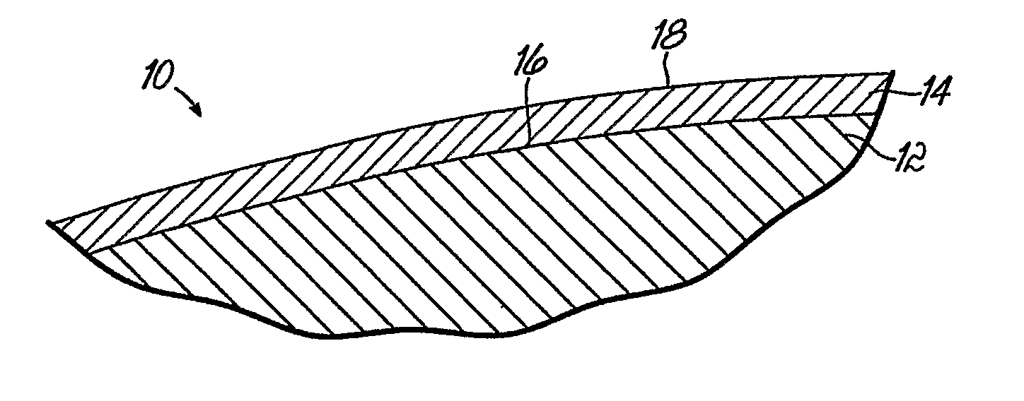
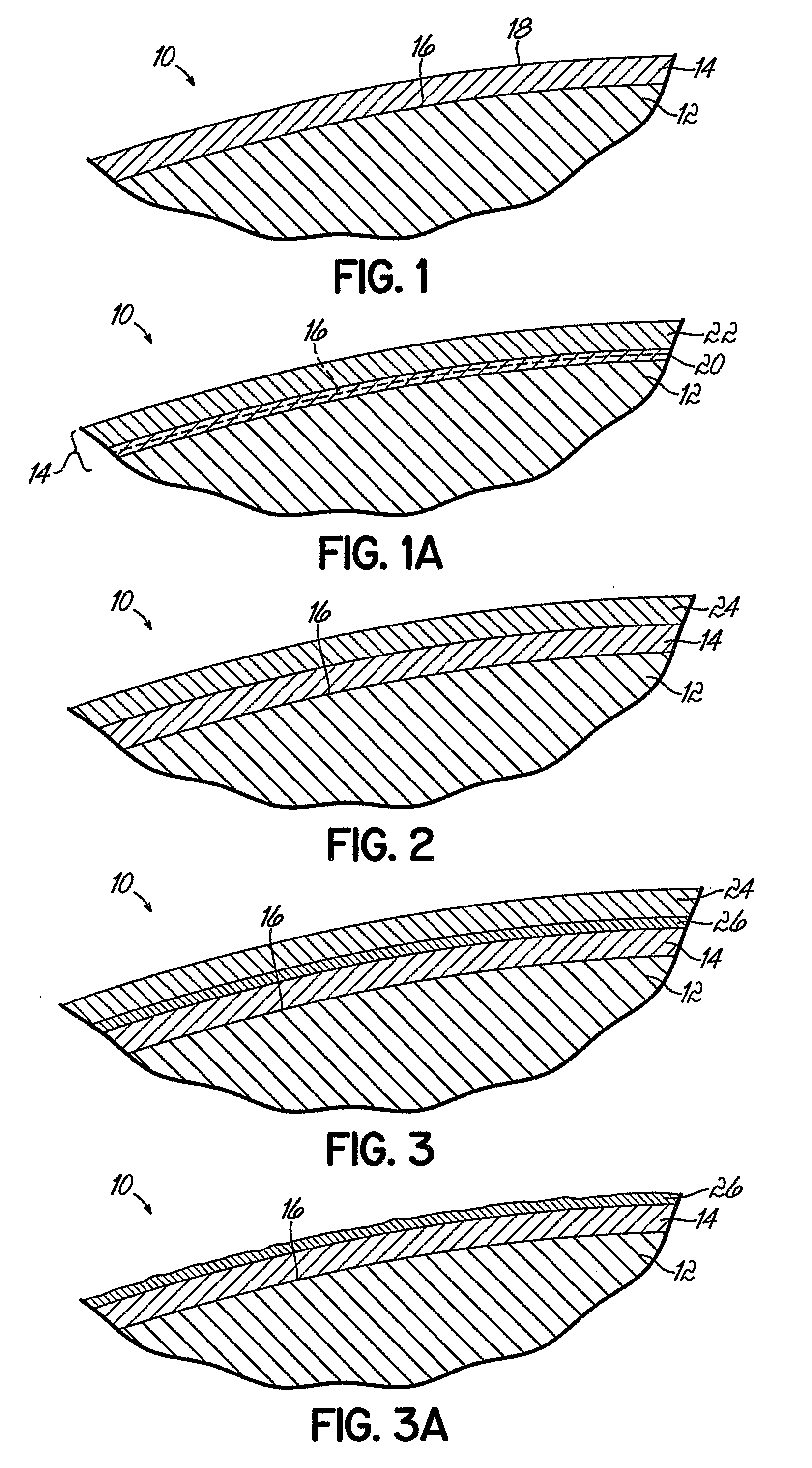
[0023]With reference to FIG. 1, a detailed view of a portion of a much larger gas turbine engine component, generally indicated by reference numeral 10, is shown. The gas turbine engine component 10 includes a metallic substrate 12 and an aluminide coating 14 coating an original surface 16 of the substrate 12. The metallic substrate 12 is made of any nickel-, cobalt-, or iron-based high temperature superalloy from which such gas turbine engine components 10 are commonly made. The base element, typically nickel or cobalt, is by weight the single greatest element in the superalloy. For example, where the component 10 is a gas turbine component in a jet engine, substrate 12 may be the nickel-based superalloy Inconel 795 Mod5A. The present invention is, however, not intended to be limited to any particular gas turbine engine component 10, which may be a turbine blade, a vane, a nozzle guide, or any other part requiring protection from high temperature oxidation and corrosion while opera...


PUM

PropertyMeasurementUnit
temperaturesaaaaaaaaaa
temperatureaaaaaaaaaa

Abstract

A turbine engine component (10) with a protective aluminide coating (14) that include additions of silicon and a dopant, such as yttrium and / or hafnium, in an amount effective to reduce sulfidation and a deposition process for forming such aluminide coatings (14). A silicon-containing layer (30) may be applied to the superalloy substrate (12) of the component (10) and the aluminide coating (14) formed by exposing component (10) and layer (30) to a vapor phase reactant containing the dopant. The aluminide coating (14), which contains dopant from the layer (30), may operate as a standalone environmental coating or as a bond coating for an optional ceramic thermal barrier layer (24). An optional zirconia layer (26) maybe provided between the aluminide coating (14) and the ceramic thermal barrier layer (24). Alternatively, the dopant may be included in the silicon-containing layer (30) applied to the component (10) before the aluminide coating (14) is formed and no vapor phase reactant containing the dopant is required.

Description

CROSS-REFERENCE TO RELATED APPLICATIONS[0001]This application is a continuation-in-part of PCT / US2004 / 041896, filed on Dec. 13, 2004, which is a continuation-in-part of application Ser. No. 10 / 943,116, filed Sep. 16, 2004, the disclosure of each of which is hereby fully incorporated by reference herein in its entirety.FIELD OF THE INVENTION[0002]The present invention relates to coated metal components and, more particularly, gas turbine engine components with an aluminide coating and methods of forming such aluminide coatings on gas turbine engine components.BACKGROUND OF THE INVENTION[0003]Intermetallic layers and coatings are often formed on a surface of a metal component to protect the underlying metal substrate of the component and to extend its useful life during operation. For example, many superalloy components in gas turbine engines, like turbine blades, vanes, and nozzle guides, include an aluminide coating on airflow surfaces that protects the underlying superalloy base me...

Claims


Application Information

Patent Timeline
Patent Type & Authority Applications(United States)
IPC IPC(8): C23C10/02C23C28/00
CPCC23C10/02Y10T428/12611C23C18/1204C23C18/1216C23C18/1225C23C18/1279C23C18/1295Y02T50/67C23C28/321C23C28/325C23C28/3455C23C6/00Y10T428/1259Y10T428/12549Y10T428/1275C23C18/06Y02T50/60
Inventor FAIRBOURN, DAVID C.
Owner AEROMET TECH
Why Eureka
Try Eureka