Hollow rack, hollow rack end diameter reducing method, hollow rack end diameter reducing apparatus, and hollow rack manufacturing method

a technology of end diameter and reducing method, which is applied in the direction of heat treatment apparatus, furnaces, gearing, etc., can solve the problem that the hardness of the end portion 203 cannot be intensified for thread cutting, and achieve the effect of reducing the number of processing steps and reducing the diameter of the end portion

Active Publication Date: 2008-09-25
NETUREN CO LTD
View PDF5 Cites 8 Cited by
  • Summary
  • Abstract
  • Description
  • Claims
  • Application Information

AI Technical Summary

Benefits of technology

[0017]An object of the present invention is to provide a hollow rack end portion diameter reducing method, apparatus and a h

Problems solved by technology

However, although the shaft portion 201 can be supplied with a higher hardness by heat

Method used


Image

  • Hollow rack, hollow rack end diameter reducing method, hollow rack end diameter reducing apparatus, and hollow rack manufacturing method
  • Hollow rack, hollow rack end diameter reducing method, hollow rack end diameter reducing apparatus, and hollow rack manufacturing method
  • Hollow rack, hollow rack end diameter reducing method, hollow rack end diameter reducing apparatus, and hollow rack manufacturing method

Examples


first embodiment

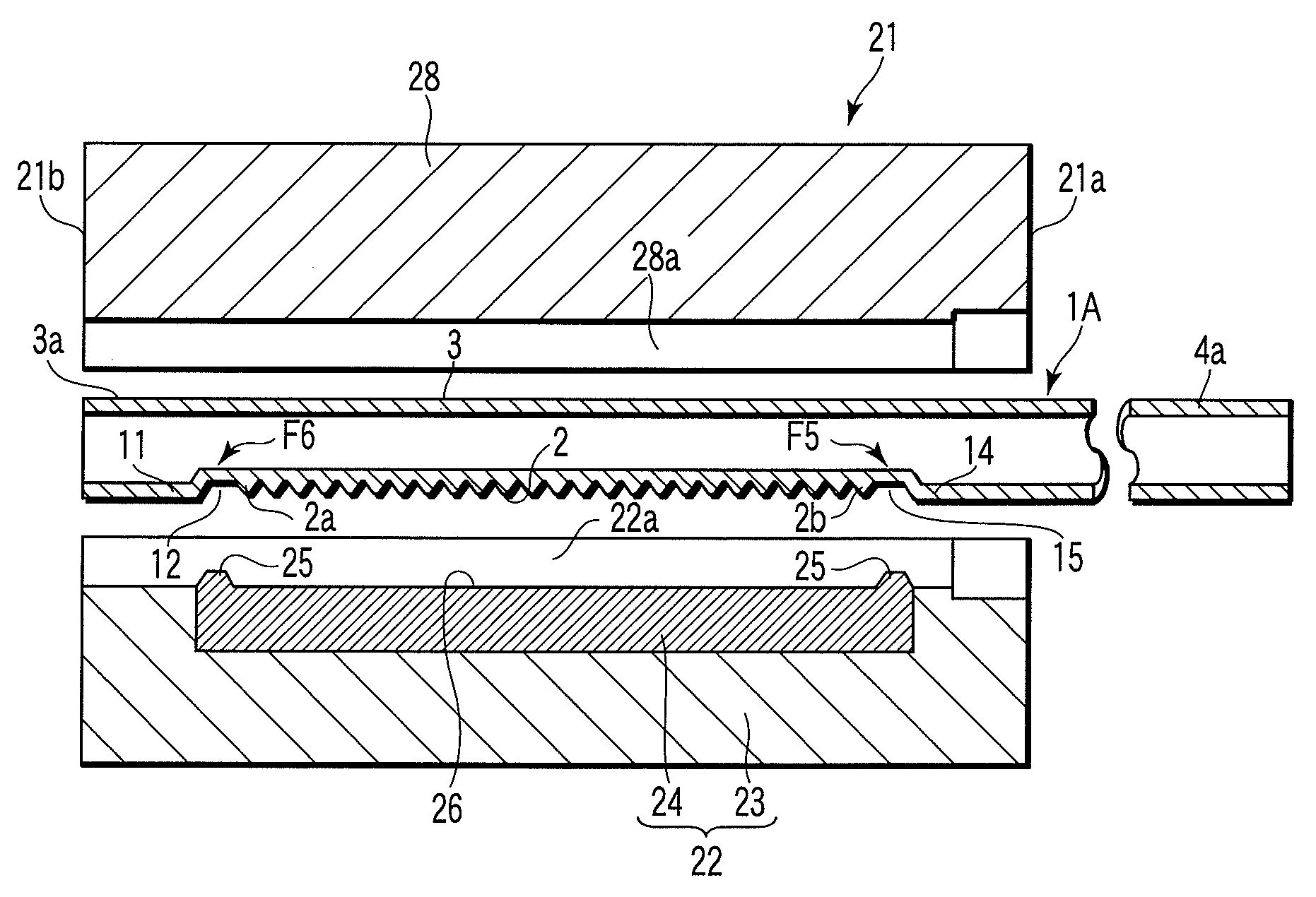
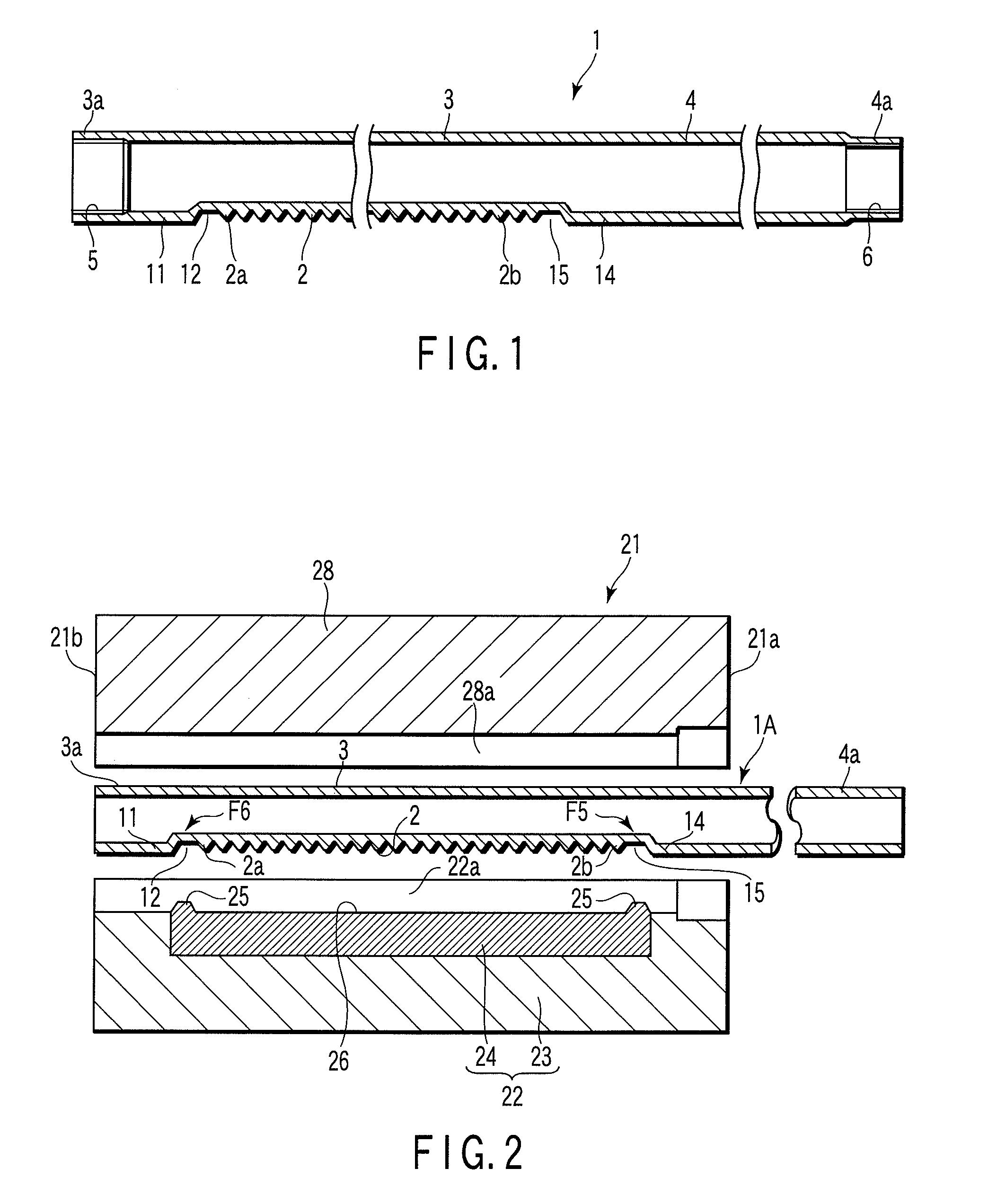
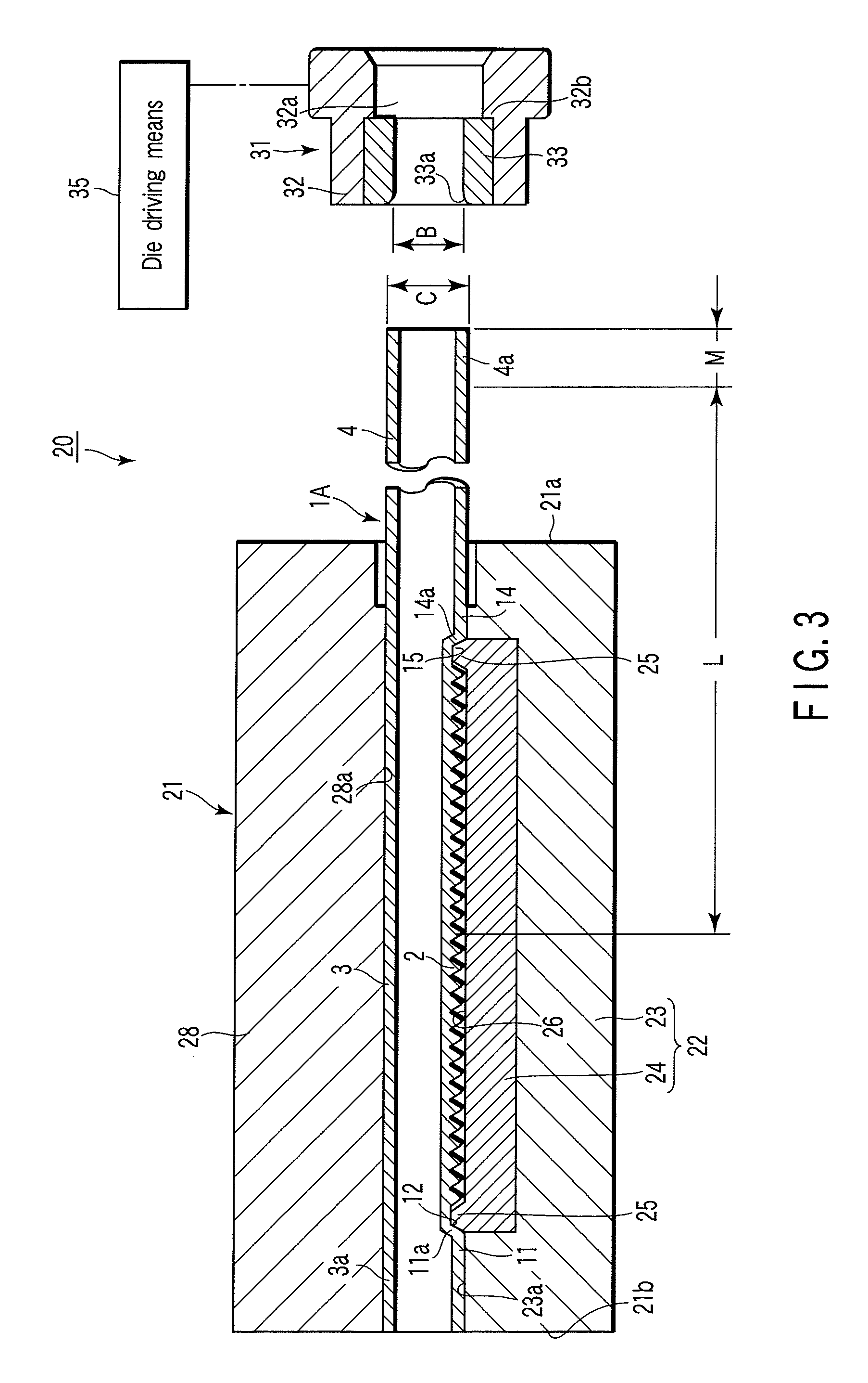
[0070]FIGS. 1 to 8 are diagrams showing the present invention. Reference number 1 in FIG. 1 denotes a hollow rack (hereinafter referred to as rack) for use as a hollow steering rack shaft of an automotive power steering system. Both ends in a direction of extension of the axis of the rack 1 (hereinafter referred to as axial direction) are open.

[0071]A rack 2 is formed in the outer face of a portion near an opening at one end of the rack 1. This rack 2 is formed by arranging plural rack teeth in the axial direction of the rack 1. The rack 2 is formed on the outer face of a processing wall portion provided by crushing part of a tubular wall near an opening at one end of a steel pipe which is a raw material of the rack 1 into a flat surface by pressing inward of the steel pipe. This rack 2 is formed by plastically fluidizing the flesh of a processing wall portion by pressing toward the tooth die of a second die from inside of the steel pipe using plural core metals each having a differ...

second embodiment

[0102]FIG. 9 is a longitudinal sectional view showing major portions of a rack and pinion incorporating a hollow rack 110 according to the present invention. The hollow rack 110 has a tubular shaft portion 111, and a tooth portion 112 which meshes with a pinion 130 is formed in an intermediate portion of this axial portion 111. Further, a threaded portion 115 for connecting to a ball joint is provided on the inner peripheral faces of a tooth side end portion 113 and a shaft side end portion 114 positioned on both ends. The hollow rack 110 is formed of for example, such material as SMn433 and its initial hardness is Hv155 to 200.

[0103]On the other hand, a ball joint 120 is attached to the tooth side end portion 113 via a socket 121. The socket 121 has an outer threaded portion 122 which is screwed with the threaded portion 115. The socket 121 is structured to support the ball joint 120 swingably and includes resin seat 123. In the meantime, reference number 140 in FIG. 9 denotes casi...


PUM

PropertyMeasurementUnit
Diameteraaaaaaaaaa
Hardnessaaaaaaaaaa

Abstract

The one end side portion is nipped by a jig including a jig member having a pair of convex portions which are to be fitted to a depressions in contact with a tooth side face and a inclined portion and positioning a bar and a jig member which is to be clamped/opened with respect to the jig member. A die having an inside diameter smaller than the diameter of the outer periphery is pressed onto the outer periphery of the end portion of the cylindrical end side portion projected from the jig up to a press-in depth determined preliminarily based on the rack, so as to reduce the diameter of the end portion.

Description

CROSS-REFERENCE TO RELATED APPLICATIONS[0001]This application is based upon and claims the benefit of priority from prior Japanese Patent Applications No. 2007-073625, filed Mar. 20, 2007; and No. 2007-085678, filed Mar. 28, 2007, the entire contents of both of which are incorporated herein by reference.BACKGROUND OF THE INVENTION[0002]1. Field of the Invention[0003]The present invention relates to a hollow rack for use as a steering rack in a traveling body having wheels, for example, automotive steering system and a method and an apparatus for reducing the diameter of an end portion of this rack. Further, the present invention relates to a method for manufacturing the hollow rack for use in a rack and pinion used in an automotive power steering system or the like and a hollow rack, particularly to increasing the strength of an end portion including a screw portion.[0004]2. Description of the Related Art[0005]Conventionally, there has been known a method and an apparatus for formin...

Claims


Application Information

Patent Timeline
IPC IPC(8): F16H1/04B23P15/14
CPCB21C5/003C21D9/0068B62D3/126B21D41/04B21K1/767Y10T29/49474Y10T29/49476Y10T29/49622B23P15/14B21K1/768C21D9/32F16H55/26Y10T74/1967
Inventor YAMAWAKI, TAKASHISUZUKI, RYOSUKEMURATA, TETSUJIYAMAMOTO, TSUYOSHIKIYOSAWA, YUTAKA
Owner NETUREN CO LTD
Why Eureka
Try Eureka