

Method and Structure for Implementing Control of Mechanical Flexibility With Variable Pitch Meshed Reference Planes Yielding Nearly Constant Signal Impedance
- Summary
- Abstract
- Description
- Claims
- Application Information
AI Technical Summary
Benefits of technology
Problems solved by technology
Method used
Image

Examples
Embodiment Construction
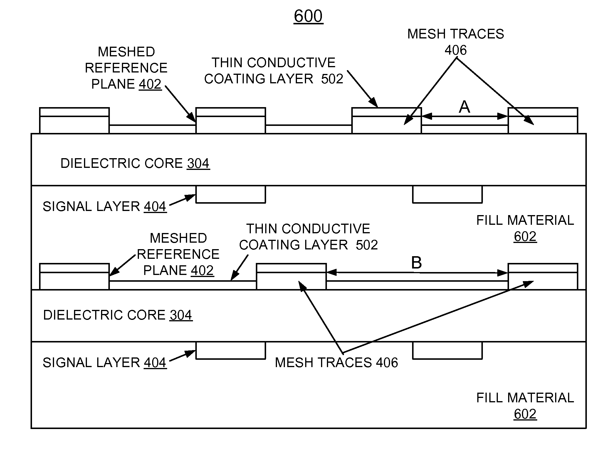
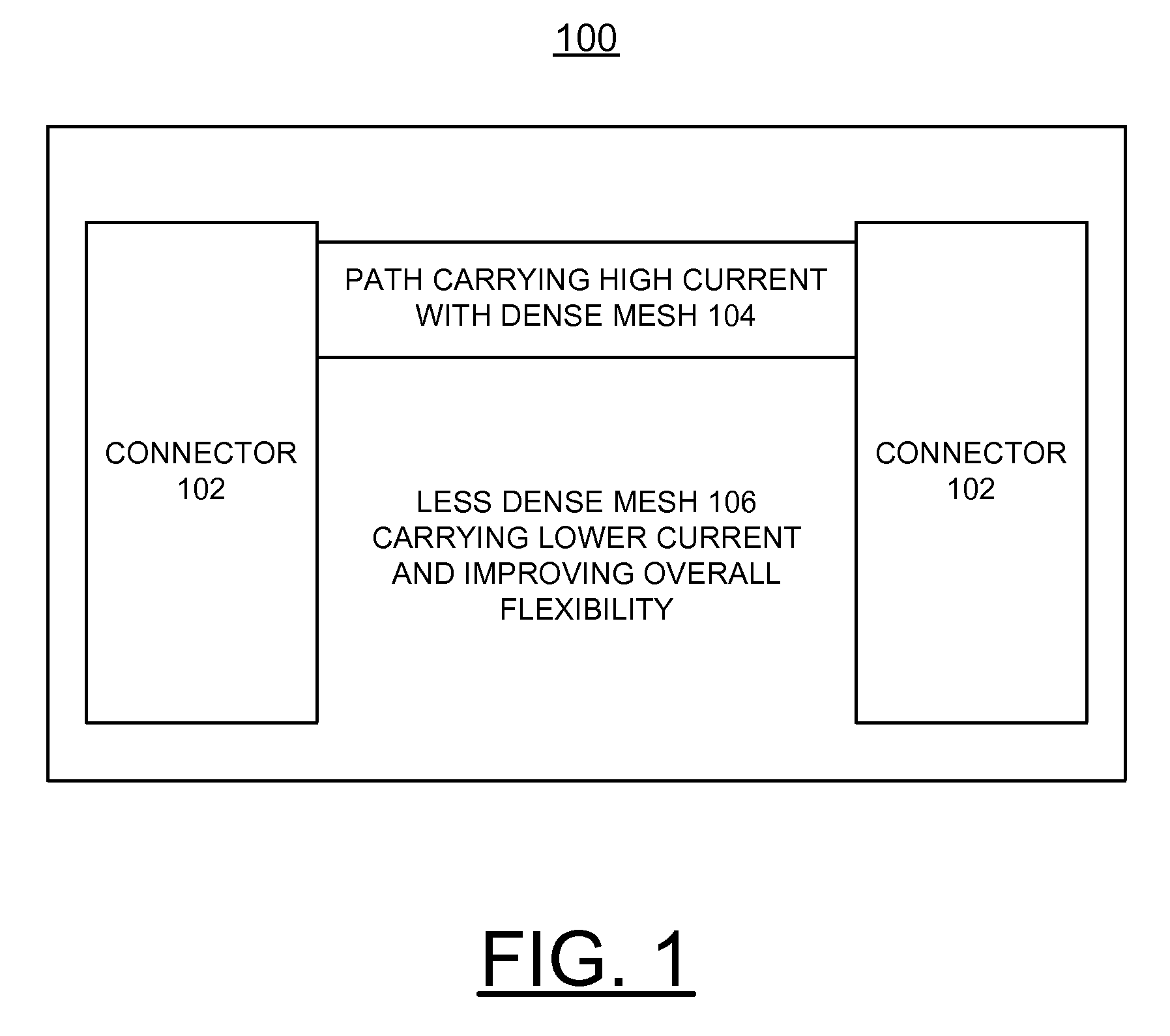
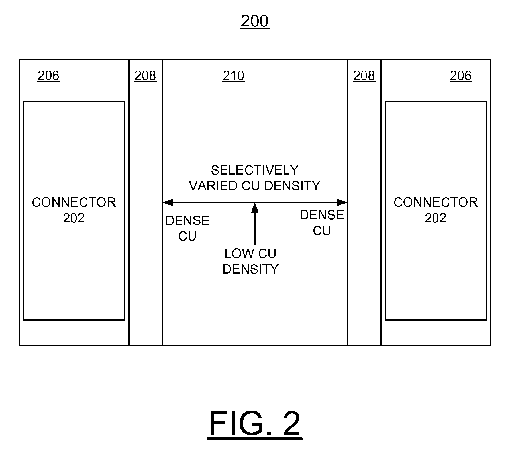
[0018]In accordance with features of the invention, a reference plane is provided which behaves electrically almost like a solid reference, while behaving mechanically like a meshed reference. That is, the reference plane is highly flexible, yet the wiring impedance is nearly constant regardless of mesh pitch and direction of the wire with respect to the mesh. Additionally, this invention allows the designer to control the mechanical flexibility of the circuit through layout of the power planes.
[0019]A structure of the invention is a meshed reference plane with a very thin conducting layer deposited, typically deposited by sputtering, over the mesh before lamination to the next core assembly. In accordance with features of the invention, significant advantages are provided over a fixed pitch mesh, or a standard solid reference in a flex circuit application. Primarily, the advantage of this invention is that it enables a significant improvement in wireability of flexible circuits or ...
PUM
| Property | Measurement | Unit |
|---|---|---|
| Thickness | aaaaa | aaaaa |
| Dielectric polarization enthalpy | aaaaa | aaaaa |
| Electrical conductivity | aaaaa | aaaaa |
Abstract
Description
Claims
Application Information