Method and Arragement for Advanced Routing Metrics in Multihop Networks

a multi-hop network and advanced routing technology, applied in the field of routing in communication networks, can solve the problems of packets experiencing long delays, classical wireline hop metric is unsuitable in a wireless environment, and the path or route determination can be very complex, so as to achieve the effect of determining link cost, high capacity, and preferably determining link cos

Active Publication Date: 2008-09-25
TELEFON AB LM ERICSSON (PUBL)
View PDF8 Cites 58 Cited by
  • Summary
  • Abstract
  • Description
  • Claims
  • Application Information

AI Technical Summary

Benefits of technology

[0025]The inventors have envisioned a multihop network scenario in which nodes are equipped with advanced multi-antenna arrangements, and especially a scenario with a diverse flora of relaying nodes and end-user terminals equipped with different antenna arrangements. The inventors have recognized the advantage of exploring the presence of such advanced antenna arrangements in multihop network nodes not only for providing high capacity over fading channels but also for the purpose of determining link cost for route determination or routing in the network. A basic idea of the invention is therefore to determine link cost for a wireless link between a pair of nodes in the network based on multi-channel characteristics between the nodes, where at least one of the nodes is configured for operation with multiple antennas to provide for multiple channels.
[0026]Link cost

Problems solved by technology

Packet forwarding is normally relatively straightforward, whereas path or route determination can be very complex.
A classical wireline hop metric is unsuitable in a wireless environment, basically since it does not reflect the link quality dependency with respect to distance.
This is not a bad metric, but it may lead to a

Method used


Image

  • Method and Arragement for Advanced Routing Metrics in Multihop Networks
  • Method and Arragement for Advanced Routing Metrics in Multihop Networks
  • Method and Arragement for Advanced Routing Metrics in Multihop Networks

Examples


Embodiment Construction

[0050]Throughout the drawings, the same reference characters will be used for corresponding or similar elements.

Introduction

[0051]The invention is generally applicable to any routing protocol, independent of implementation, including both distributed and centralized routing algorithms, hop-by-hop routing as well as source-routing, link-state routing and distance-vector routing (also sometimes referred to as Bellman-Ford algorithm based), proactive or reactive routing, flat or hierarchical routing, single path and multipath routing, as well as variations and combinations thereof.

[0052]For more information on routing techniques, especially in wireless ad hoc networks, reference can be made to [2].

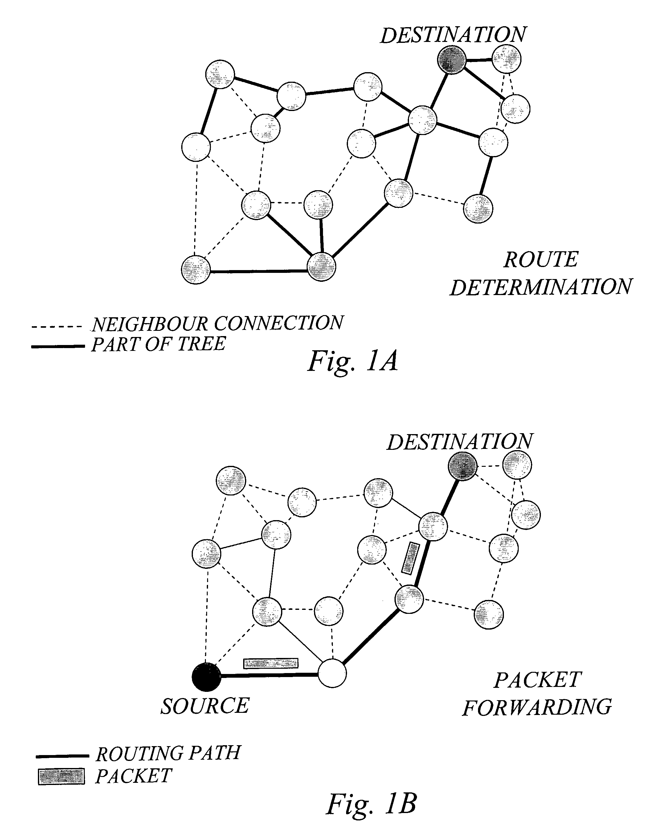
[0053]In source-routing it is normally assumed that the source end node determines the entire route. The intermediate nodes then merely act as store-and-forward units, mindlessly forwarding the packet to the next node on the path to the destination node.

[0054]In hop-by-hop routing, each node ...


PUM


Abstract

The inventors have envisioned a multihop network scenario in which nodes are equipped with advanced multi-antenna arrangements, and recognized the advantage of exploring the presence of such advanced antenna arrangements in multihop network nodes for the specific purpose of determining link cost for routing in the network. A basic idea of the invention is therefore to determine link cost for a wireless link between a pair of nodes in the network based on multi-channel characteristics between the nodes, where at least one of the nodes is configured for operation with multiple antennas to provide for multiple channels. These multi-channel characteristics may for example be determined based on explicit channel matrix estimation and/or the number of transmit and receive antennas or other information on the antenna capabilities of the involved nodes. The determined link cost information may subsequently be used together with additional routing cost information for route determination, and packet forwarding.

Description

TECHNICAL FIELD OF THE INVENTION[0001]The present invention generally relates to routing in communication networks such as multihop networks, and more particularly to the issue of determining appropriate link cost metrics for use in route determination and routing.BACKGROUND OF THE INVENTION[0002]In general, routing can be defined as the act of moving information from a source to a destination via one or more intermediate nodes in a communication network.[0003]When routing is applied in a wireless network, such a network is often referred to as a multihop network. In a multihop network, nodes out of reach from each other may benefit from intermediately located nodes that can forward their messages from the source towards the destination. Traditionally, multihop networks have often been associated with so called ad hoc networks where nodes are mostly mobile and no central coordinating infrastructure exists. However, the idea of multihop networking can also be applied when nodes are f...

Claims


Application Information

Patent Timeline
IPC IPC(8): H04L12/28H04L45/122
CPCH04L45/00H04L45/123Y02B60/50H04W84/18H04W40/06Y02D30/70
Inventor LARSSON, PETERJOHANSSON, NIKLASHU, RONGZHANG, ZHANG
Owner TELEFON AB LM ERICSSON (PUBL)
Why Eureka
Try Eureka