Tunable Laser

a laser and tunable technology, applied in the field of tunable lasers, can solve the problems of difficult to maintain the laser oscillation with a constant wavelength, high price due to an increase in the number of elements, and difficult to put them into practical use, so as to achieve high reliability, reduce the influence of stray light, and simplify the manufacturing process

Active Publication Date: 2008-09-25
NEC CORP
View PDF13 Cites 37 Cited by
  • Summary
  • Abstract
  • Description
  • Claims
  • Application Information

AI Technical Summary

Benefits of technology

[0011]In the laser element where the tuning mechanism is provided outside the laser element, mode jump is easily generated by the oscillation. Thus, it requires a large-scaled oscillation-resistant mechanism for avoiding the mode jump, which results in large-scaled module and increased price.
[0025]Furthermore, the use of the laser structure according to the present invention achieves the tuning action over a wide range of wavelengths that cannot be achieved with a regular DFB-LD, through a simple structure using no external mirror that has bee used conventionally. Furthermore, there is no movable part provided therein unlike the regular tunable laser of the external mirror type. Thus, high oscillation impact characteristic can be achieved in addition to achieving high reliability. Moreover, the change in the property over time is extremely smaller compared to the system that injects electric current to the semiconductor waveguide since the refractive indexes of the ring-type waveguides of the ring resonator are changed for tuning the wavelengths. As has been described above, the tunable laser according to the present invention is superior to the conventional tunable laser in many respects, and it can be manufactured at a low cost. Therefore, it is an extremely effective structure to be put into practical use.

Problems solved by technology

However, even though there have been a great number of structures proposed as the conventional tunable lasers, there are shortcomings such as generation of mode hopping, complicated method of wavelength control, low oscillation resistibility, high price due to an increase in the number of elements, etc.
Therefore, it has been still difficult to put them into a practical use.
Therefore, it is difficult to maintain the laser oscillation with a constant wavelength over a long time.
Furthermore, with the current process technique of a compound semiconductor, inch-up of two inches or more is impossible.
Thus, it is difficult to cut the cost from that of the current state with the laser element that has become complicated and large-scaled.
Thus, it requires a large-scaled oscillation-resistant mechanism for avoiding the mode jump, which results in large-scaled module and increased price.

Method used


Image

  • Tunable Laser
  • Tunable Laser
  • Tunable Laser

Examples


first embodiment

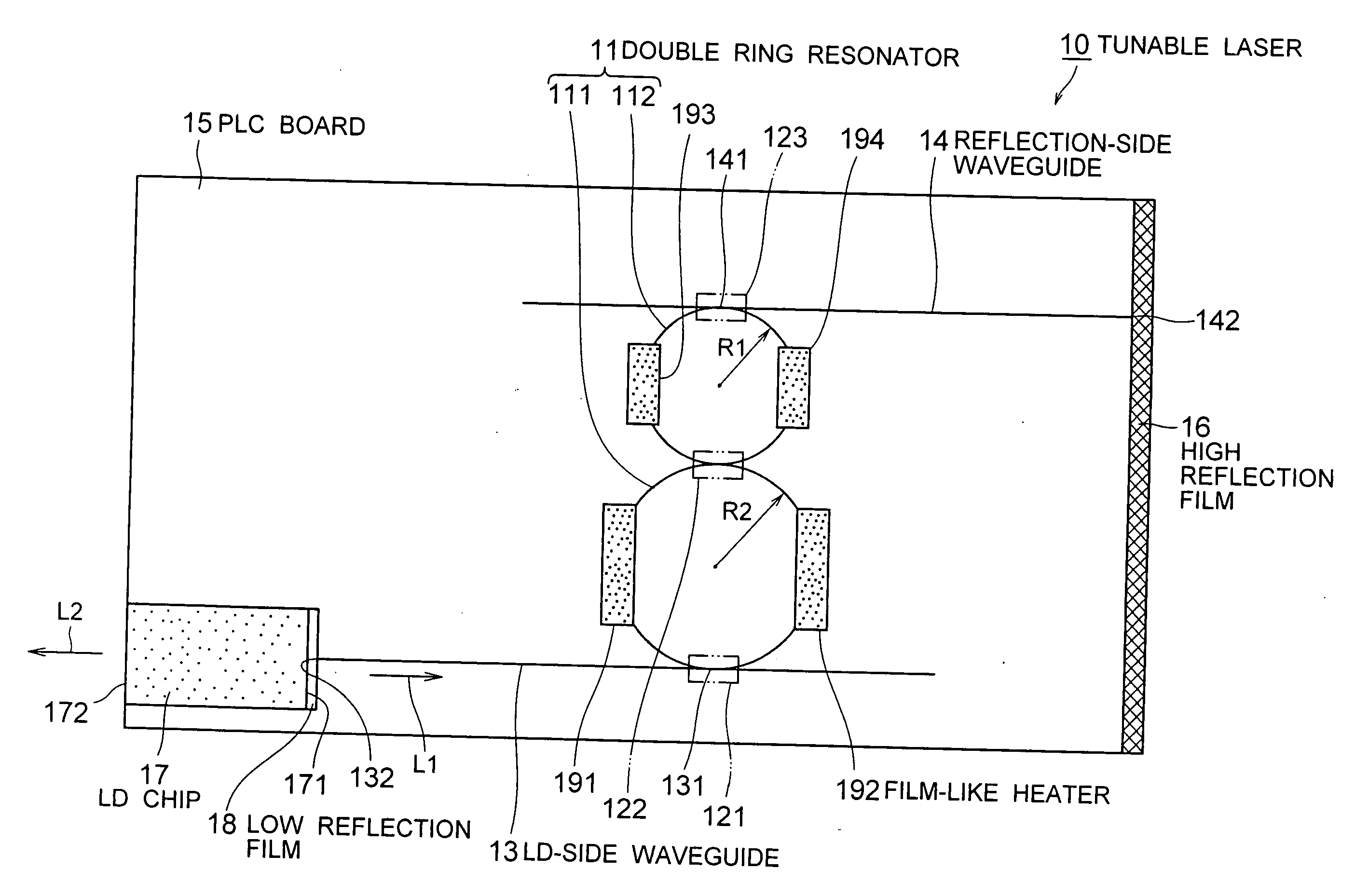
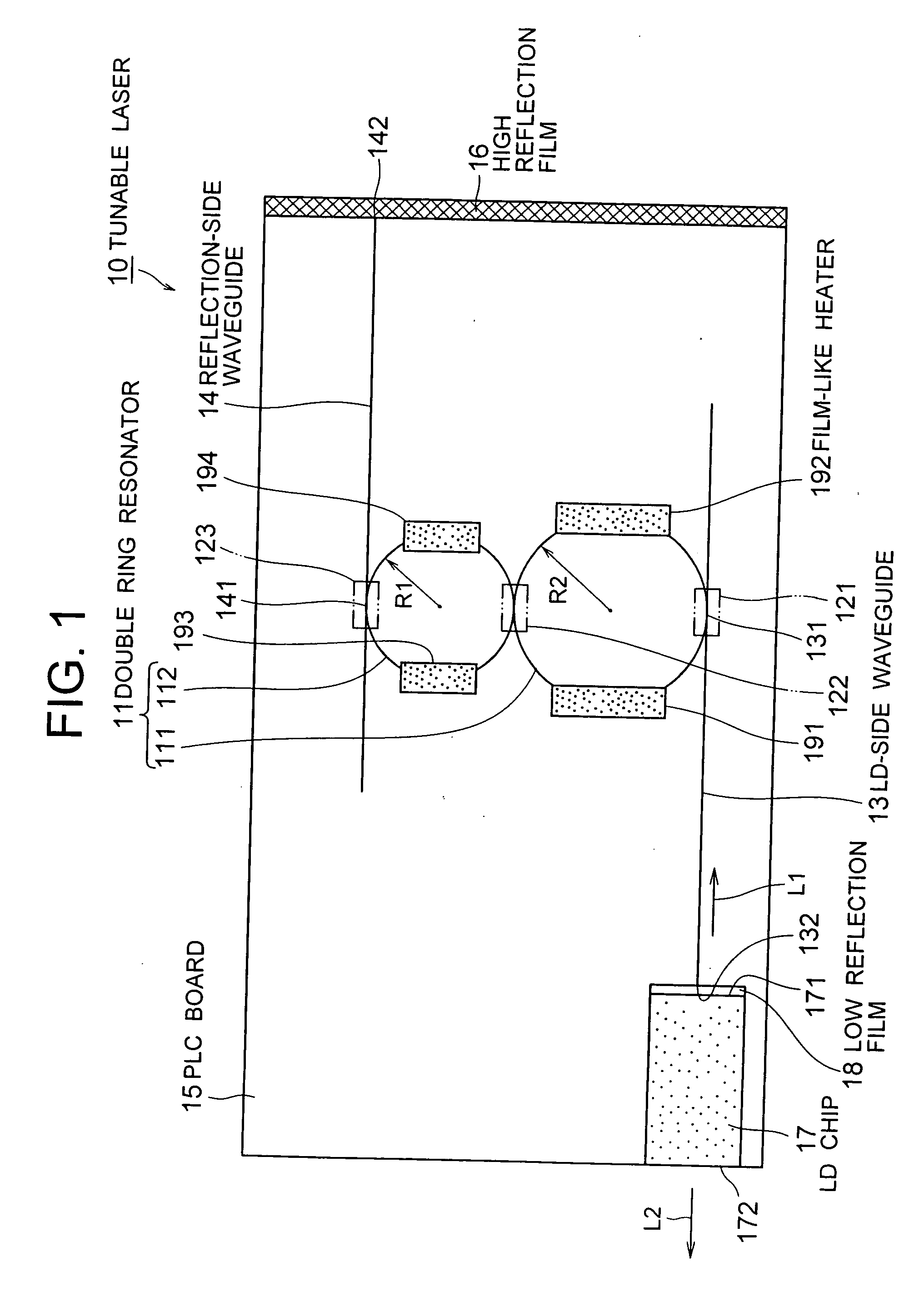
[0038]FIG. 1 is a plan view for showing the tunable laser according to the present invention. There will be a description provided hereinafter by referring to this illustration.

[0039]A tunable laser 10 according to this embodiment comprises: a double ring resonator 11 in which ring resonators 111, 112 that are formed with ring-type waveguides of different optical path lengths from each other are coupled through a directional coupler 122; an LD-side waveguide 13 whose one end 131 is connected to the ring resonator 111 through a directional coupler 121; a reflection-side waveguide 14 whose one end 141 is connected to the ring resonator 112 through a directional coupler 123; a single PLC board 15 on which the ring resonators 111, 112, the LD-side waveguide 13, and the reflection-side waveguide 14 are formed; a high reflection film 16 provided on other end 142 of the reflection-side waveguide 14; an LD chip 17 formed on the PLC board 15, which has a low reflection film 18 formed on one ...

second embodiment

[0051]FIG. 4 is a plan view for showing the tunable laser according to the present invention. There will be description provided hereinafter by referring to the drawing. The same reference numerals are applied to the same components as those of FIG. 1, and the description thereof will be omitted.

[0052]The tunable laser 20 according to this embodiment comprises bent parts 134, 144 formed at one end 131 of the LD-side waveguide 13 and one end 141 of the reflection-side waveguide 14 for directing, towards a prescribed direction, the end faces 133, 143 that are extended therefrom. With this, stray lights emitted from the end faces 134 and 143 can be guided towards the direction of less influence.

[0053]The bent parts 134 and 144 are used as the stray light suppressing parts in FIG. 4. However, it is not intended to be limited to those. Any stray light suppressing parts may be used as long as they can suppress the influence of the stray lights emitted from the end face that is extended fr...

third embodiment

[0054]FIG. 5 is a plan view for showing the tunable laser according to the present invention. There will be description provided hereinafter by referring to the drawing. The same reference numerals are applied to the same components as those of FIG. 1, and the description thereof will be omitted.

[0055]The tunable laser 30 according to this embodiment comprises a light-receiving element 31 provided on the end face 133 that is extended from one end 131 of the LD-side waveguide 13. The intensity of the laser light L2 emitted from the LD chip 17 can be monitored with the light-receiving element 31. The light-receiving element 31 is a photodiode, for example, and it is directly mounted on the PLC board 15 along with the LD chip 17 by the passive alignment technique. The light-receiving element 31 may be provided to the end face 143 that is extended from one end 141 of the reflection-side waveguide 14.


PUM

PropertyMeasurementUnit
wavelengthsaaaaaaaaaa
temperaturesaaaaaaaaaa
reflectionaaaaaaaaaa

Abstract

[Problems] To provide a tunable laser with high reliability and high performance, and of low cost.[Means for Solving Problems] A tunable laser (10) comprises a double ring resonator (11) where ring resonators (111, 112) of different sizes are coupled through a directional coupler (122), an LD side waveguide (13) connected at one end (131) to the ring resonator (111) through a directional coupler (123), a reflection side waveguide (14) connected at one end (141) to the ring resonator (112) through a directional coupler (123), a PLC board (15) on which the ring resonator (111) and the like are formed, a high reflection film (16) provided at the other end (142) of the reflection side waveguide (14), an LD chip (17) having a low reflection film (18) formed on either of two opposing emission end faces (171, 172) and coupled optically with the other end (132) of the LD side waveguide (13), and film-like heaters (191-194) for varying the resonance wavelength of the double ring resonator (11).

Description

TECHNICAL FIELD[0001]The present invention relates to a tunable laser that is used in a WDM (Wavelength Division Multiplexing) transmission system and the like, for example.BACKGROUND ART[0002]Into the era of broadband, in order to achieve efficient utilization of optical fibers, there has been more introduction of a WDM transmission system that is capable of performing communication with a plurality of optical wavelengths using a single system. Recently, it has become popular to use a DWDM apparatus (Dense Wavelength Division Multiplexing Apparatus) which multiplexes several tens of optical wavelengths and enables transmission at still higher rate. In accordance with this, each WDM transmission system requires light sources that correspond to each of the optical wavelengths, and the required numbers thereof have dramatically increased in accordance with the high-multiplexing. Furthermore, ROADM (Reconfigurable optical add / drop multiplexers) which add and drop optional wavelengths a...

Claims


Application Information

Patent Timeline
Patent Type & Authority Applications(United States)
IPC IPC(8): H01S3/10G02B6/12G02B6/34G02F1/01H01S5/00H01S5/02H01S5/0687H01S5/10H01S5/14
CPCG02B6/12004G02B6/12007G02F1/011G02F1/0147G02F2203/15H01S5/142H01S5/02446H01S5/0654H01S5/06804H01S5/0687H01S5/02248H01S5/02325H01S5/14
Inventor YAMAZAKI, HIROYUKI
Owner NEC CORP
Why Eureka
Try Eureka