Multi-Layer Piezoelectric Element and Method for Manufacturing the Same

a piezoelectric element and multi-layer technology, applied in the direction of generator/motor, machine/engine, mechanical apparatus, etc., can solve the problems of device shutdown, contact failure between the external electrode and the internal electrode, etc., to prevent the generation of cracks that penetrate through the external electrode, increase the displacement of the piezoelectric actuator, and improve durability

Active Publication Date: 2008-10-02
KYOCERA CORP
View PDF16 Cites 33 Cited by
  • Summary
  • Abstract
  • Description
  • Claims
  • Application Information

AI Technical Summary

Benefits of technology

[0020]With the first multi-layer piezoelectric element according to the present invention having the constitution described above, since each of the external electrodes is constituted from three or more layers including the first layer formed in contact with the side face of the stack and the second layer formed on the first layer, crack is contained within the interface between the three or more layers and stopped from propagating to the adjacent layers, thus the generation of crack that penetrates through the external electrode can be prevented.
[0021]Thus it is made possible to prevent the external electrode from being cracked due to dimensional change of the stack, so as to provide the multi-layer piezoelectric element of improved durability which does not experience variation in the amount of displacement even when put into continuous operation over a long period of time.
[0022]Also because the first multi-layer piezoelectric element according to the present invention has such a constitution as the inactive layer of the stack includes the metal dispersed therein, stress generated between the inactive layer and the active layer during shrinkage due to firing can be mitigated (equalized), and the amount of displacement of the piezoelectric actuator can be increased during operation under high voltage and high pressure. It is also made possible to maintain the amount of displacement constant during continuous operation over a long period of time, and improve durability during continuous operation under a high voltage over a long period of time. The method for manufacturing a multi-layer piezoelectric element according to the present invention makes it possible to easily manufacture the multi-layer piezoelectric element where a metal is dispersed in the inactive layer, since the metal layer is removed after firing the green stack which has the metal layer formed on the piezoelectric material layer.

Problems solved by technology

However, there have been such problems in the multi-layer piezoelectric element as described below, since the active layer expands and contracts while the external electrodes and the inactive layers that are formed around the active layer do not expand or contract.
First, since the active layer experiences repetitive changes in the dimension during operation, peel-off between the external electrode and the piezoelectric layer and / or crack in the external electrode may occur when the device is put into continuous operation over a long period of time in a high electric field under a high pressure, eventually resulting in contact failure in the junction between the external electrode and the internal electrode.
This may cause the failure in applying voltage to some of the piezoelectric layers and, after being used over a long period of time, lead to variation in the displacement characteristics or spark which causes the device to shut down.
In recent years, such problems as described above have become conspicuous since it is a common practice to operate the multi-layer piezoelectric element continuously with a higher electric field over a long period of time, as it is required to achieve a large amount of displacement from a compact multi-layer piezoelectric element.
Although the inactive layer disclosed in Patent Document 3 mitigates the difference in the degree of shrinkage between the active layer and the inactive layer, there remains a problem related to durability since cracks tend to occur in the interface between the electrode 61 that constitutes the inactive layer 62 and the piezoelectric layer (active layer) 63 when the device is put into continuous operation over a long period of time with a high voltage applied thereto.

Method used


Image

  • Multi-Layer Piezoelectric Element and Method for Manufacturing the Same
  • Multi-Layer Piezoelectric Element and Method for Manufacturing the Same
  • Multi-Layer Piezoelectric Element and Method for Manufacturing the Same

Examples


first embodiment

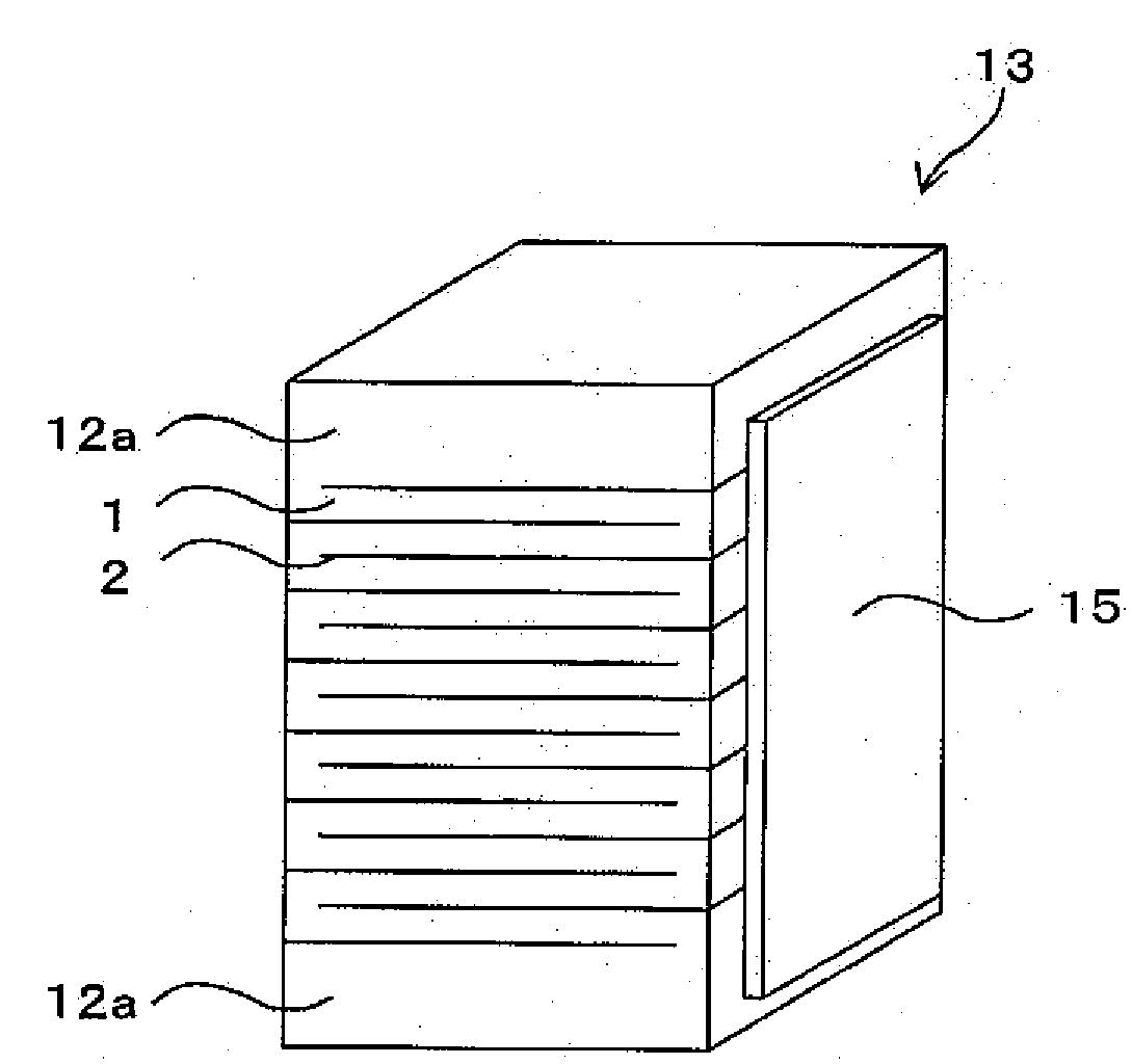
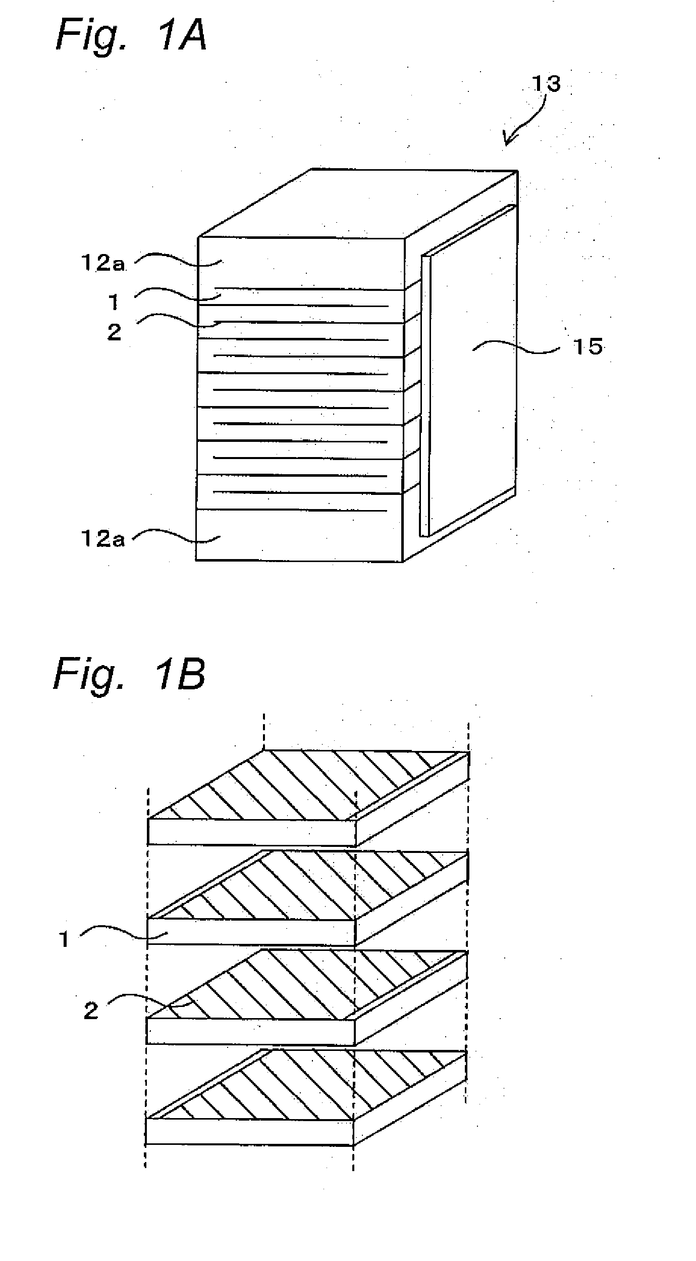
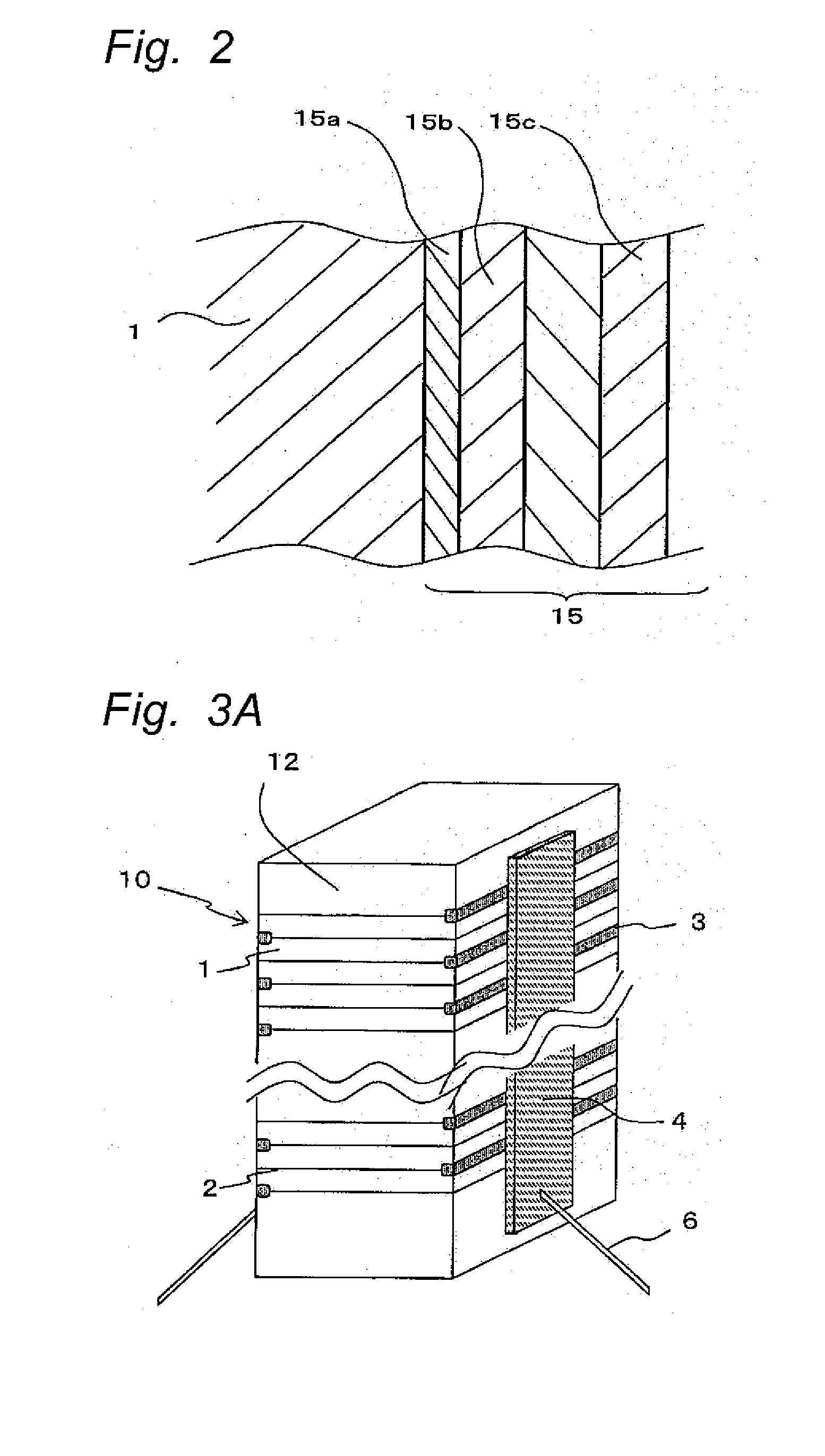
[0054]FIG. 1A and FIG. 1B show the constitution of a multi-layer piezoelectric element according to the first embodiment of the present invention, FIG. 1A being a perspective view and FIG. 1B being an exploded perspective view showing piezoelectric layers and internal electrodes being stacked. FIG. 2 is an enlarged sectional view showing multi-layer structure of an external electrode formed on a side face of the piezoelectric layer in the multi-layer piezoelectric element of the present invention.

[0055]In the multi-layer piezoelectric element according to the first embodiment, as shown in FIG. 1A and FIG. 1B, the external electrodes 15 are formed on a pair of opposing side faces of a stack 13 constituted from the piezoelectric layers 1 and the internal electrodes 2 placed alternately one on another. An end of the internal electrode 2 is exposed on the side face of the stack 13 where the external electrode 15 is formed in every other layer, and the external electrode 15 is connected ...

second embodiment

[0088]A multi-layer piezoelectric element according to second embodiment of the present invention will now be described.

[0089]The multi-layer piezoelectric element of the second embodiment is similar to the multi-layer piezoelectric element of the first embodiment in the constitution of the active portion 11 of the stack 10, but is distinguished in the constitution of the inactive layer 12.

[0090]FIG. 3A and FIG. 3B show the constitution of the multi-layer piezoelectric element according to the second embodiment of the present invention, FIG. 3A being a perspective view and FIG. 3B being a sectional view showing an active portion consisting of internal electrode layers and piezoelectric layers stacked one on another and protective layer.

[0091]As shown in FIG. 3A and FIG. 3B, the multi-layer piezoelectric element according to the second embodiment has such a constitution as groove is formed to provide insulation between the external electrode 4 and the internal electrode 2 in every ot...

third embodiment

[0152]An injection apparatus according to the present invention will now be described. The injection apparatus is constituted by using the multi-layer piezoelectric element of the present invention.

[0153]FIG. 6 shows an injection apparatus according to the present invention, where a container 31 has an injection hole 33 formed at one end thereof, and a needle valve 35 that can open and close the injection hole 33 is housed in the container 31.

[0154]The injection hole 33 is provided with a fuel passage 37 disposed in communication therewith. The fuel passage 37 is connected to a fuel source that is provided outside of the apparatus, so as to receive supply of fuel at a high pressure that remains always constant. When the needle valve 35 opens the injection hole 33, the fuel that fills the fuel passage 37 is injected at a predetermined level of high pressure into a fuel chamber of an internal combustion engine that is not shown in the drawings.

[0155]The needle valve 35 has an enlarged...


PUM

PropertyMeasurementUnit
thicknessaaaaaaaaaa
thicknessaaaaaaaaaa
thicknessaaaaaaaaaa

Abstract

The multi-layer piezoelectric element comprises a stack having an active portion constituted from at least one piezoelectric layer and a plurality of internal electrodes consisting of first and second internal electrodes placed one on another, the active portion being subjected to expansion and contraction in response to a voltage applied across the first internal electrode and the second internal electrode, and external electrodes formed on two side faces of the stack with one thereof being connected to the first internal electrode and the other connected to the second internal electrode, wherein each of the external electrodes is constituted from three or more layers including a first layer formed in contact with the side face of the stack and a second layer formed on the first layer, to provide a multi-layer piezoelectric element having high durability.

Description

FIELD OF THE INVENTION[0001]The present invention relates to a multi-layer piezoelectric element (may be hereinafter referred to simply as an “element”) used in, for example, fuel injection apparatus of automobile engine, liquid injection apparatus of ink jet printer or the like or a drive unit used in precision positioning device or vibration preventing device for an optical apparatus, and to a multi-layer piezoelectric element used as a sensor element mounted in combustion pressure sensor, knocking sensor, acceleration sensor, load sensor, ultrasound sensor, pressure sensor, yaw rate sensor or the like, or used as a circuit component mounted in piezoelectric gyro, piezoelectric switch, piezoelectric transducer, piezoelectric breaker or the like.BACKGROUND ART[0002]Multi-layer piezoelectric actuators constituted from piezoelectric layers and internal electrodes stacked alternately one on another have been known. The multi-layer piezoelectric actuators can be divided into two catego...

Claims


Application Information

Patent Timeline
Patent Type & Authority Applications(United States)
IPC IPC(8): H01L41/047H01L41/22F02M51/00F02M51/06F02M63/00H01L41/083H02N2/00
CPCF02M51/0603Y10T29/42H01L41/083H01L41/0472H10N30/872H10N30/50
Inventor NAKAMURA, SHIGENOBUTSURUMARU, TAKAFUMIOKAMURA, TAKESHI
Owner KYOCERA CORP
Why Eureka
Try Eureka